4-Way Compression Grooved Coupling

Inactive Publication Date: 2011-06-30
SHURJOINT METALS INC
View PDF5 Cites 78 Cited by
  • Summary
  • Abstract
  • Description
  • Claims
  • Application Information

AI Technical Summary

Benefits of technology

[0014]What is needed, in order to raise efficiency of installation work, is a new type coupling to solve those technical problems, while

Problems solved by technology

If gasket ID B is actually slightly larger than the pipe OD as shown in FIG. 3, the gasket can easily be mounted onto the

Method used


Image

  • 4-Way Compression Grooved Coupling
  • 4-Way Compression Grooved Coupling
  • 4-Way Compression Grooved Coupling

Examples


Embodiment Construction

[0037]Turning now to the drawings, the invention will be described in a preferred embodiment by reference to the numerals of the drawing figures wherein like numbers indicate like parts.

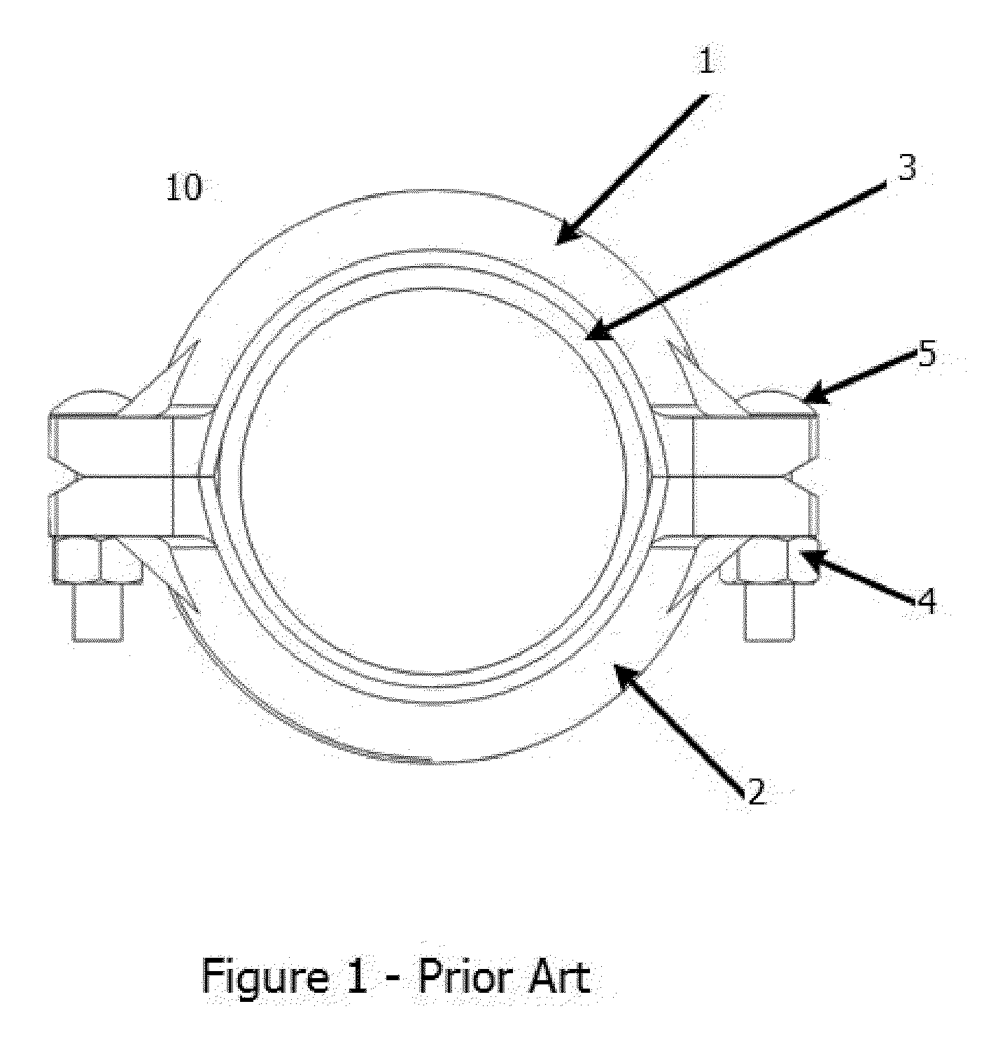
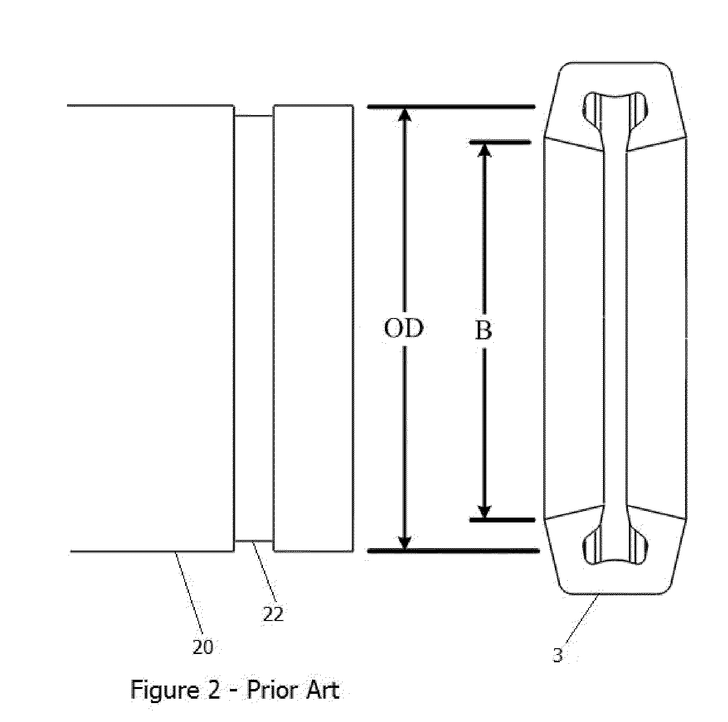
[0038]FIGS. 1 and 2 illustrate typical features of some conventional pipe couplings. Coupling 10 has upper and lower arcuate segments 1 and 2, both enclosing gasket 3, and fastened together by bolts 5 and nuts 4. Pipe 20 fitted with end grooves 22 is shown for comparison of diameters with gasket 3. Conventional pipe gasket 3, especially if provided as a one-piece gasket, has an inner diameter B that is less than the outer diameter OD of pipe 20. This has been reported to optimize sealing of gasket 3 on pipe 20. The problem is that gasket 3 must first be stretched onto the end of pipe 20, with attendant effort and risk of tearing or gouging or dropping gasket 3, and with potential insurmountable difficulty when at least one pipe end is already in a hard to reach location.

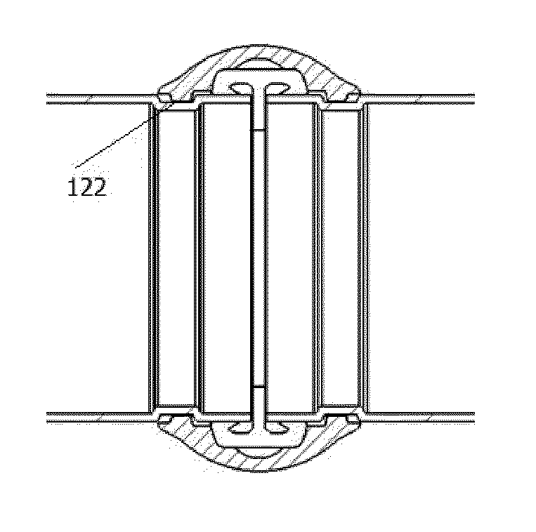
[0039]FIG. 3 shows an unconven...


PUM

PropertyMeasurementUnit
Angleaaaaaaaaaa
Angleaaaaaaaaaa
Angleaaaaaaaaaa

Abstract

A pre-assembled pipe coupling for joining and sealing two grooved-ended pipe segments without disassembling the coupling is disclosed. The coupling has a housing with upper and lower arcuate housing segments and left and right bridge segments. Each bridge segment has at least one set of dihedrally angled faces that engage corresponding faces each in the upper and lower housing segments. Drawing the upper and lower segments inwardly together along a first axis, presses each bridge segment inward along a second axis roughly tangential to the first axis. All segments are loosely pre-assembled with bolts and nuts into a coupling and all segments each have radially inwardly projecting lands that mate with end grooves in the pipes to be joined. The coupling also has a one-piece circular sealing gasket that has an inward circumferential and centrally positioned pipe stop that has an inner diameter smaller than an outer diameter of the pipes to be joined. The gasket has two circumferential sealing lips axially outward from the pipe stop, the inner diameter each sealing lip larger than the outer diameter of the pipe segments to be joined.
Method for joining and sealing two grooved-ended pipe segments with a pre-assembled pipe coupling, without disassembling the coupling, is also disclosed.

Description

[0001]This application claims priority to U.S. Provisional Application 61 / 265,327 filed Nov. 30, 2009.TECHNICAL FIELD[0002]The invention relates to pipe joints; more particularly, it relates to housing type pipe couplings for creating a sealed connection between coaxial groove ended pipes.BACKGROUND[0003]Housing type pipe couplings are widely used for axially joining two pipes together in such a way as to create a non-leaking union between the pipe ends. To prevent leakage, it is often desirable to prevent longitudinal, angular or rotational movement of the pipe ends within the coupling. This type of coupling is called a rigid coupling[0004]Generally, the coupling is formed of arcuate housing segments which are fastened around the pipe ends to form a generally ring-like coupling housing. Typically, two segments are used, a pair of arcuate or generally semicircular housing halves, which are fastened together, often bolted together. Housing halves are substantially U- or C-shaped in l...

Claims


Application Information

Patent Timeline
IPC IPC(8): F16L17/00B23P11/00
CPCY10T29/49863Y10T29/49826B23P19/022Y10T29/49908Y10T29/49927F16L23/08F16L17/04Y10T29/49925
Inventor HAGIYA, HOWARD
Owner SHURJOINT METALS INC
Why Eureka
Try Eureka