Exhaust system

a technology of exhaust system and exhaust pipe, which is applied in the direction of engine components, mechanical equipment, machines/engines, etc., can solve the problems of prolonging the service life of the entire exhaust system, and achieve the effect of reducing the tendency to development and allowing for greater freedom of design

Inactive Publication Date: 2011-08-11
EBERSPACHER EXHAUST TECH GMBH & CO KG
View PDF7 Cites 3 Cited by
  • Summary
  • Abstract
  • Description
  • Claims
  • Application Information

AI Technical Summary

Benefits of technology

[0007]The present invention pertains to the object of proposing for an exhaust system with a heating means an improved or at least different embodiment, which is characterize

Problems solved by technology

This advantageously leads to a prolongation of

Method used


Image

  • Exhaust system
  • Exhaust system
  • Exhaust system

Examples


Embodiment Construction

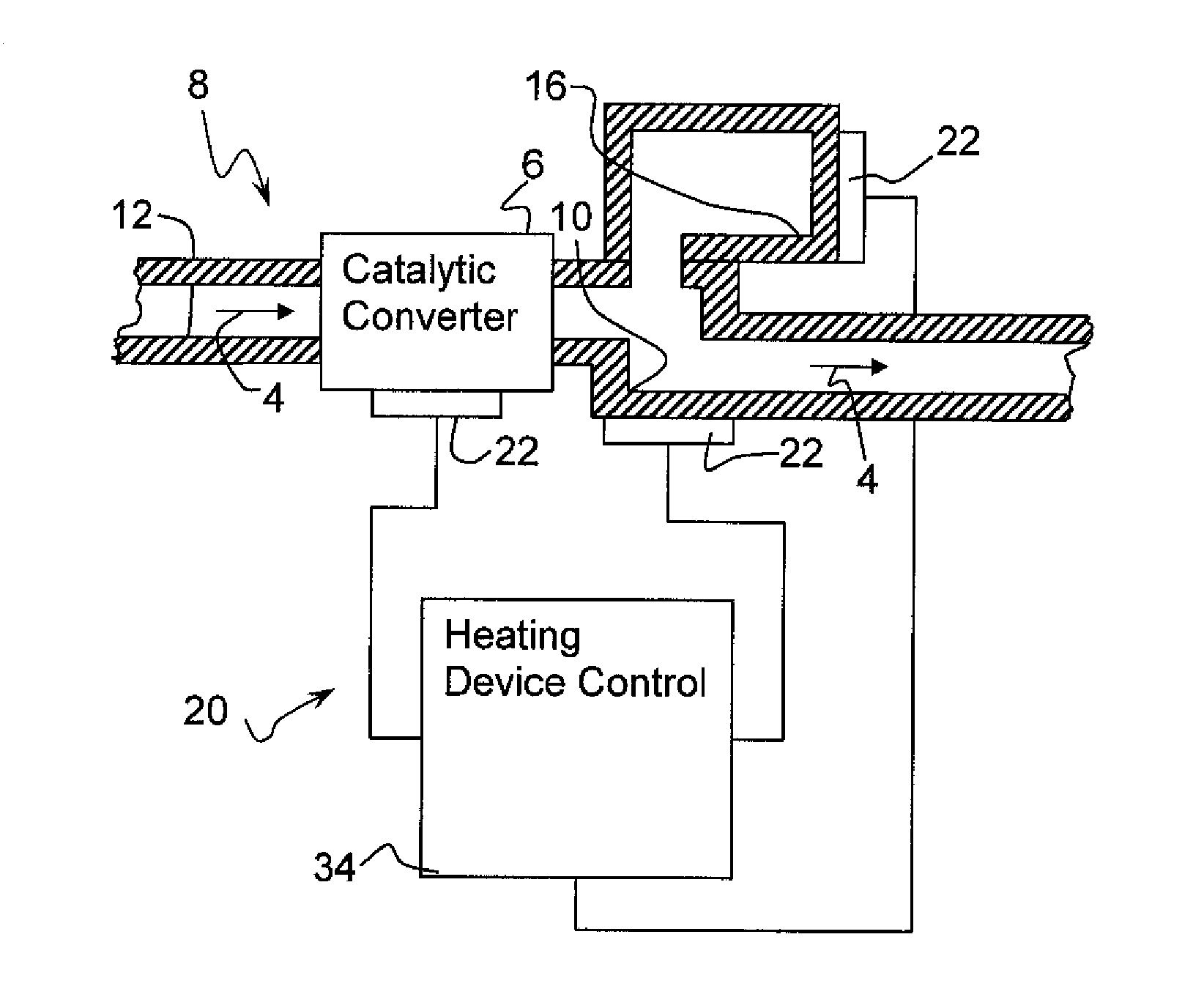
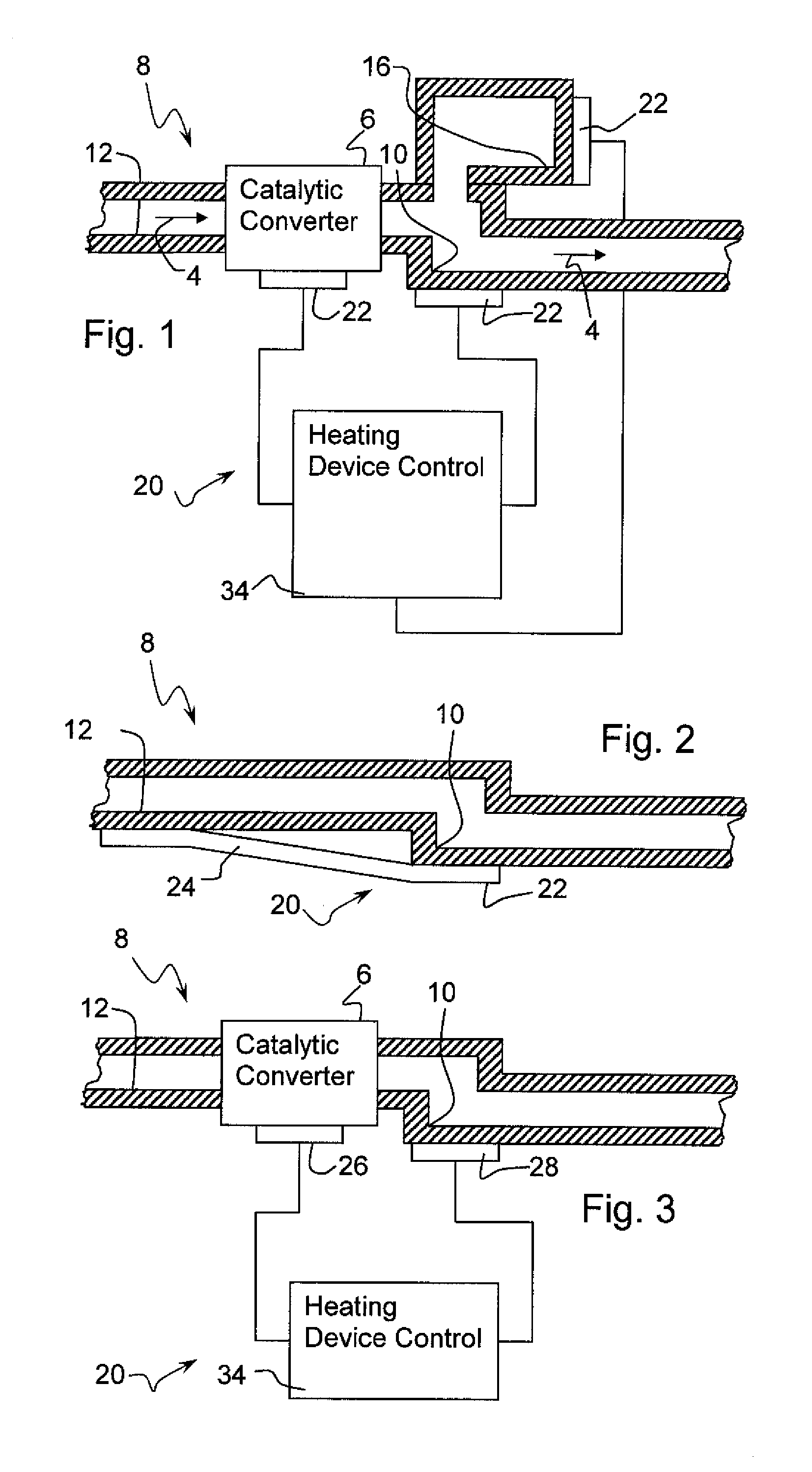
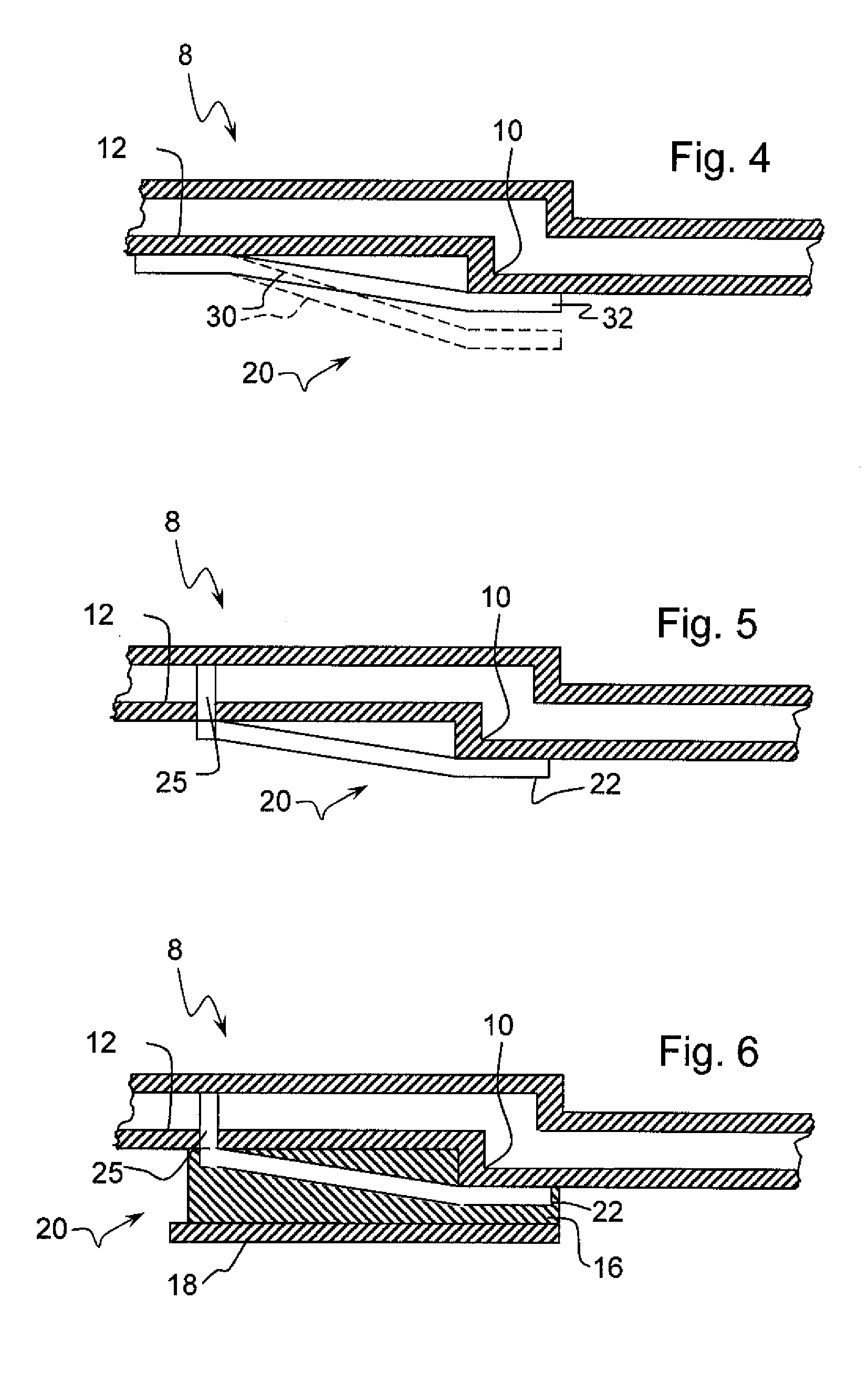
[0017]Referring to the drawings in particular, FIG. 1 schematically shows a section of an exhaust system 8 of a motor vehicle. The exhaust system 8 is shown with a flow passage, through which exhaust gas flows as indicated by arrows 4, having a wall with an exhaust system area 10 in which condensate accumulates and in which accumulation of condensate may take place depending on operating states and / or environmental parameters. The exhaust system 8 has a higher temperature area 12 which has a temperature higher than the temperature of the area 10 in which condensate accumulates to said area in which condensate accumulates.

[0018]A heating means 20 for the exhaust system may have a plurality of heating devices 22, which may be arranged in different positions at the exhaust system and which have different functionalities concerning the heating of the exhaust system. For example, a heating device 22 may thus be positioned in the area of a catalytic converter 6 arranged in the exhaust sys...


PUM


Abstract

An exhaust system, especially of a motor vehicle has at least one heating device positioned in an area in which condensate accumulates, which is arranged within the exhaust system and in which condensate can accumulate depending on operating states and/or environmental parameters. The formation of condensate accumulation is reduced or prevented by the heating device and a condensate accumulation already formed is removed. As a consequence of the corrosive property of the condensate, the service life of the exhaust system is increased by the removal of such condensate accumulations or by preventing such accumulations from forming. At the same time, the freedom of designing the exhaust system concerning the location and position of the individual components is increased.

Description

CROSS REFERENCE TO RELATED APPLICATIONS[0001]This application claims the benefit of priority under 35 U.S.C. §119 of German Patent Application DE 10 2010 007 013.0 filed Feb. 5, 2010, the entire contents of which are incorporated herein by reference.FIELD OF THE INVENTION[0002]The present invention pertains to an exhaust system, especially of a motor vehicle.BACKGROUND OF THE INVENTION[0003]Combustion water, which may lead to problems on the components of the exhaust system, for example, during wintertime operation, is formed during the combustion of fuels. Depending on the composition of the fuel, a volume of combustion water may be released by the combustion, which is comparable to the volume of fuel consumed. This combustion water generated is usually blown off as vapor together with the hot exhaust gases via the exhaust system during the normal medium-load operation of the motor vehicle. However, the temperature may drop below the dew point and liquid combustion water may precip...

Claims


Application Information

Patent Timeline
IPC IPC(8): F01N3/02F01N5/02
CPCF01N1/02F01N1/065F01N3/005F01N5/02F01N13/00Y02T10/20F01N13/16F01N13/18F01N2390/00Y02T10/16F01N13/14Y02T10/12
Inventor WIRTH, GEORG
Owner EBERSPACHER EXHAUST TECH GMBH & CO KG
Why Eureka
Try Eureka