Systems and methods for cervical seal

a cervical seal and system technology, applied in the field of electronic surgical methods and devices, can solve problems such as perforation or other damage of the uterine cavity

Inactive Publication Date: 2011-08-25
MINERVA SURGICAL
View PDF12 Cites 36 Cited by
  • Summary
  • Abstract
  • Description
  • Claims
  • Application Information

AI Technical Summary

Benefits of technology

[0007]The following presents a simplified summary of some embodiments of the invention in order to provide a basic understanding of the invention. This summary is not an extensive overview of the invention. It is not intended to identify

Problems solved by technology

The uterine cavity may be perforated or otherwise damaged by the transc

Method used


Image

  • Systems and methods for cervical seal
  • Systems and methods for cervical seal
  • Systems and methods for cervical seal

Examples


Embodiment Construction

[0040]In the following description, various embodiments of the present invention will be described. For purposes of explanation, specific configurations and details are set forth in order to provide a thorough understanding of the embodiments. However, it will also be apparent to one skilled in the art that the present invention may be practiced without the specific details. Furthermore, well-known features may be omitted or simplified in order not to obscure the embodiment being described.

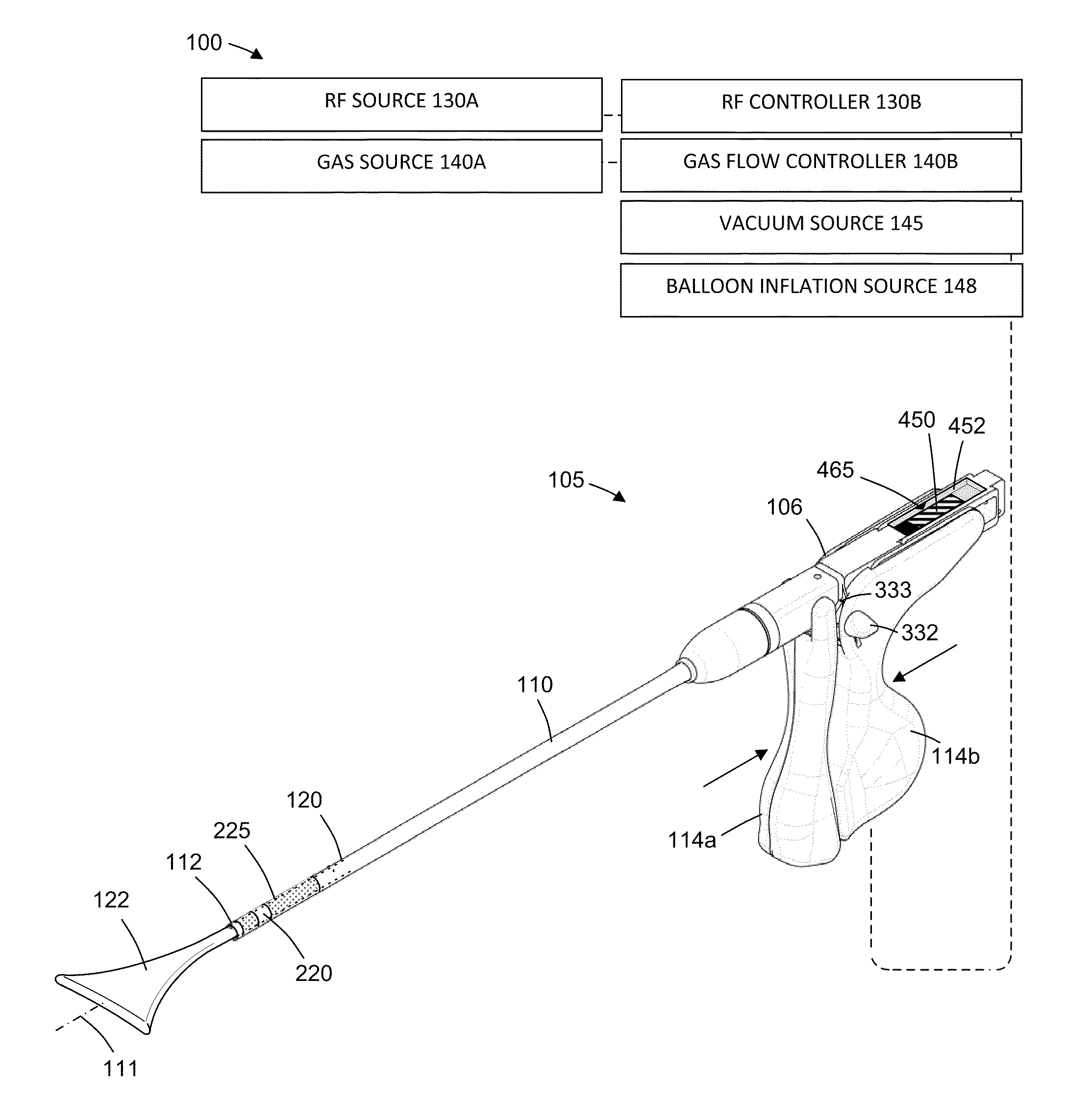
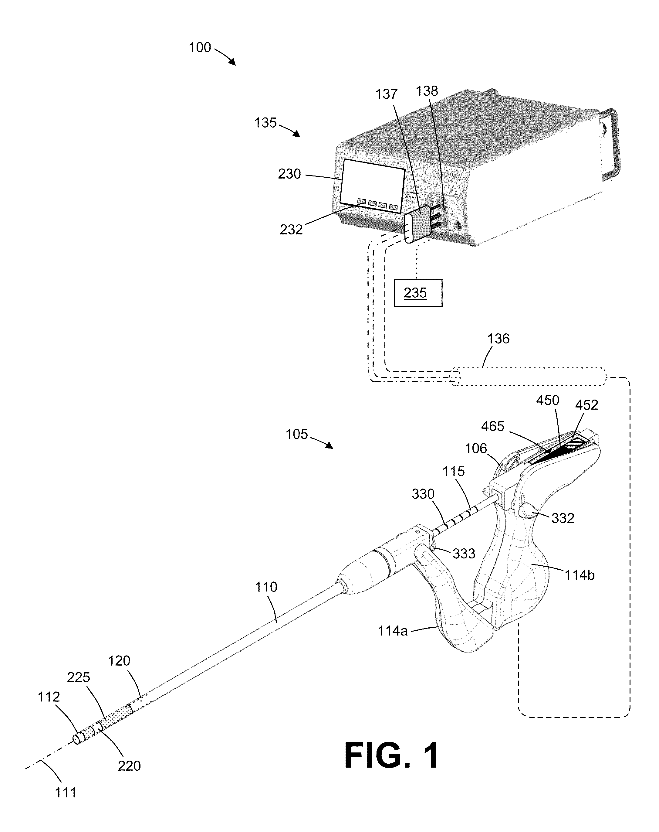
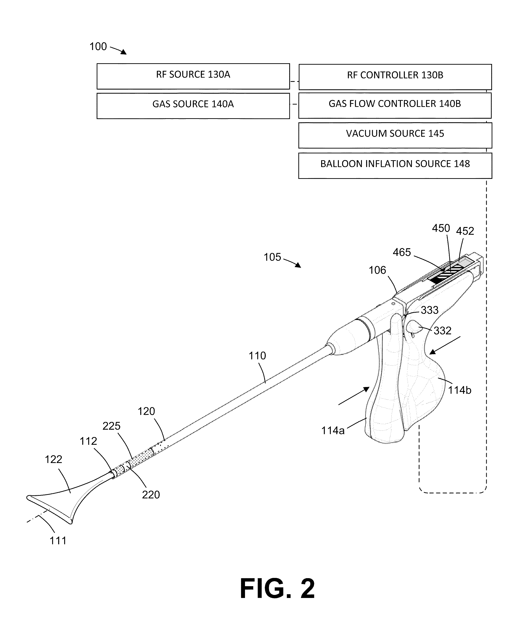
[0041]In general, an electrosurgical ablation system is described herein that comprises an elongated introducer member for accessing a patient's uterine cavity with a working end that deploys an expandable thin-wall dielectric structure containing an electrically non-conductive gas as a dielectric. In one embodiment, an interior chamber of the thin-wall dielectric structure contains a circulating neutral gas such as argon. An RF power source provides current that is coupled to the neutral gas flow...


PUM


Abstract

Methods, systems and devices for endometrial ablation. In accordance with a method, a working end of an RF ablation device is positioned in a patient uterus to contact endometrial tissue, the working end comprising a dielectric wall capable of non-expanded and expanded shapes. A sealing member is deployed in the cervical canal during ablation.

Description

BACKGROUND[0001]1. Field of the Invention[0002]The present invention relates to electrosurgical methods and devices for global endometrial ablation in a treatment of menorrhagia. More particularly, the present invention relates to applying radiofrequency current to endometrial tissue by means of capacitively coupling the current through an expandable, thin-wall dielectric member enclosing an ionized gas.[0003]A variety of devices have been developed or proposed for endometrial ablation. Of relevance to the present invention, a variety of radiofrequency ablation devices have been proposed including solid electrodes, balloon electrodes, metalized fabric electrodes, and the like. While often effective, many of the prior electrode designs have suffered from one or more deficiencies, such as relatively slow treatment times, incomplete treatments, non-uniform ablation depths, and risk of injury to adjacent organs.[0004]For these reasons, it would be desirable to provide systems and method...

Claims


Application Information

Patent Timeline
IPC IPC(8): A61B18/14A61B18/18
CPCA61B18/042A61B18/1485A61B2018/0022A61B2018/147A61B2018/00559A61B2018/00577A61B2018/00232
Inventor TRUCKAI, CSABA
Owner MINERVA SURGICAL
Why Eureka
Try Eureka