Fixed-spindle and floating-platen abrasive system using spherical mounts

a technology of abrasive system and fixed plate, which is applied in the direction of grinding machine components, manufacturing tools, lapping machines, etc., can solve the problems of abrading debris being continually flushed from the abraded surface of workpieces

Inactive Publication Date: 2011-09-15
DUESCHER WAYNE O
View PDF99 Cites 25 Cited by
  • Summary
  • Abstract
  • Description
  • Claims
  • Application Information

AI Technical Summary

Problems solved by technology

The applied coolant water results in abrading debris being continually flushed from the abraded surface of the workpieces.

Method used


Image

  • Fixed-spindle and floating-platen abrasive system using spherical mounts
  • Fixed-spindle and floating-platen abrasive system using spherical mounts
  • Fixed-spindle and floating-platen abrasive system using spherical mounts

Examples


Embodiment Construction

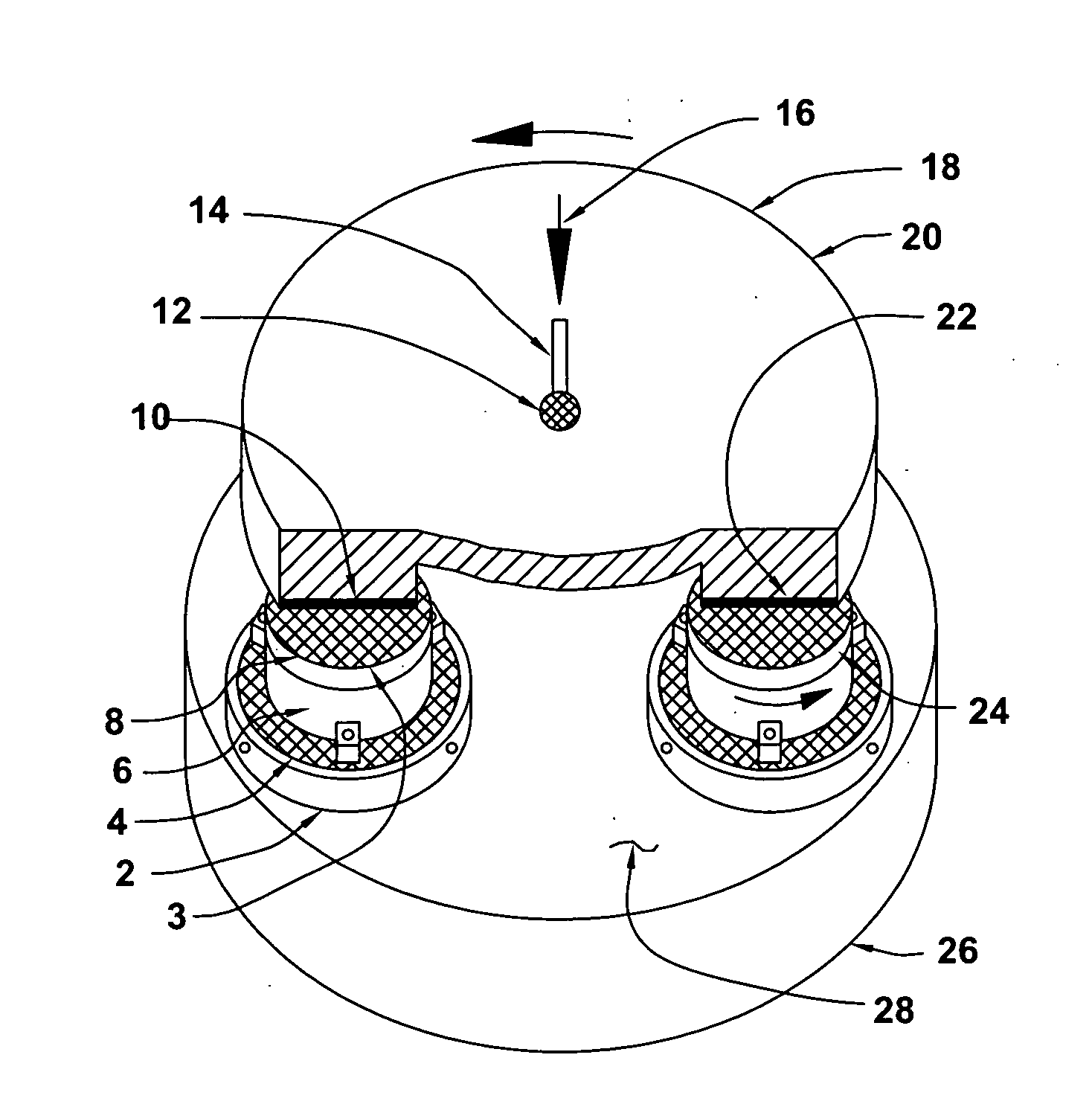
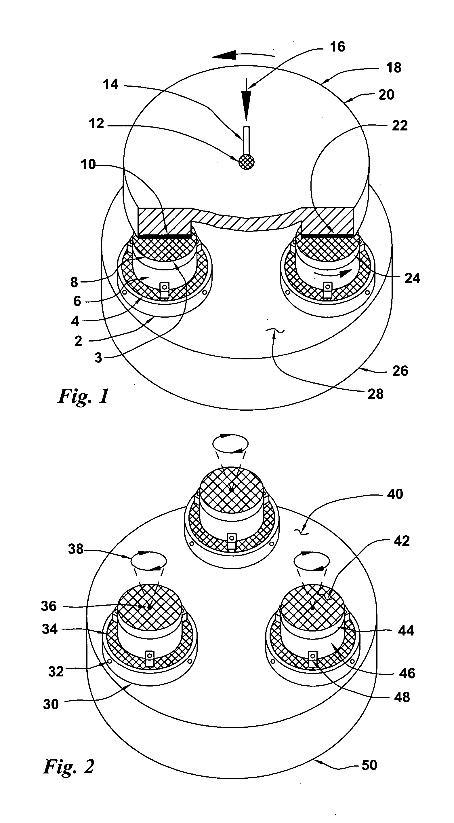
[0248]FIG. 1 is an isometric view of an abrading system 20 having three-point fixed-position rotating workpiece spindles supporting a floating rotating abrasive platen. Three evenly-spaced rotatable spherical-base mounted spindles 6 (one not shown) having rotating tops 24 that have attached workpieces 8 support a floating abrasive platen 18. The rotary spindles 6 are attached to spherical base rotors 4 that are mounted in spherical bases 2 where the spherical rotors 4 can have spherical rotation action when mounted in the spherical bases 2. The spindles 6 spherical bases 2 are attached to the nominally-flat surface 28 of the granite or epoxy-granite machine base 26. The platen 18 has a vacuum, or other, abrasive disk attachment device (not shown) that is used to attach an annular abrasive disk 22 to the precision-flat platen 18 abrasive-disk mounting surface 10. The abrasive disk 22 is in flat abrasive surface contact with all three of the workpieces 8. The rotating floating platen ...


PUM

PropertyMeasurementUnit
flatnessaaaaaaaaaa
flatnessaaaaaaaaaa
diameteraaaaaaaaaa

Abstract

A method and apparatus for releasably attaching flexible abrasive disks to a flat-surfaced platen that floats in three-point abrading contact with three flat-surfaced rotatable fixed-position workpiece spindles that are mounted on spherical-rotation two-piece spindle-mount devices that are attached to a nominally-flat abrading machine base. The spindle-top flat surfaces are precisely co-planar with each other. The three spindles are positioned to form a triangle of platen supports where the rotational-centers of each of the spindles are positioned at the center of the annular width of the platen abrading-surface. Flat surfaced workpieces are attached to the spindles and the rotating floating-platen abrasive surface contacts the workpieces to perform single-sided abrading on them. The disk abrasive surfaces can be re-flattened by attaching abrasive disk-type components to the three spindles that are rotated while in abrading contact with the rotating abrasive disk. There is no wear of the abrasive-disk protected platen surface.

Description

CROSS REFERENCE TO RELATED APPLICATION[0001]This invention is a continuation-in-part of the U.S. patent application Ser. No. 12 / 799,841 filed May 3, 2010 that is a continuation-in-part of the U.S. patent application Ser. No. 12 / 661,212 filed Mar. 12, 2010.BACKGROUND OF THE INVENTIONField of the Invention[0002]The present invention relates to the field of abrasive treatment of surfaces such as grinding, polishing and lapping. In particular, the present invention relates to a high speed lapping system that provides simplicity, quality and efficiency to existing lapping technology using a rotary abrasive floating platen that is supported by multiple fixed-position rotary workpiece spindles that have two-piece spherical-rotation spindle-mounting devices.Fixed-Spindle-Floating-Platen System[0003]The present invention relates to methods and devices for a single-sided lapping machine that is capable of flat-lapping ultra-thin semiconductor wafer workpieces at high abrading speeds. This is ...

Claims


Application Information

Patent Timeline
Patent Type & Authority Applications(United States)
IPC IPC(8): B24B1/00B24B5/313
CPCY10T29/49895B24B37/107
Inventor DUESCHER, WAYNE O.
Owner DUESCHER WAYNE O
Why Eureka
Try Eureka