

Transparent display device
- Summary
- Abstract
- Description
- Claims
- Application Information
AI Technical Summary
Benefits of technology
Problems solved by technology
Method used
Image

Examples
first embodiment
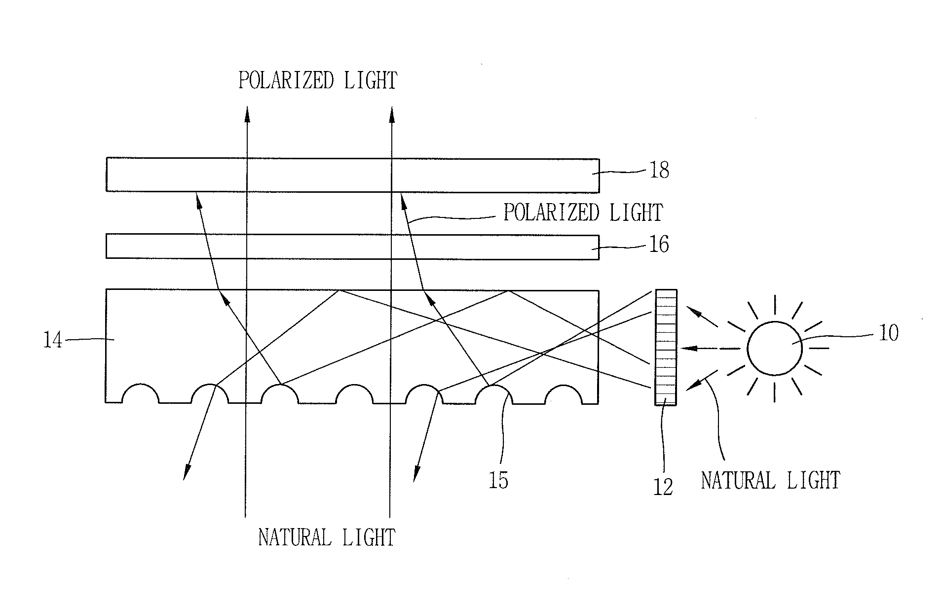
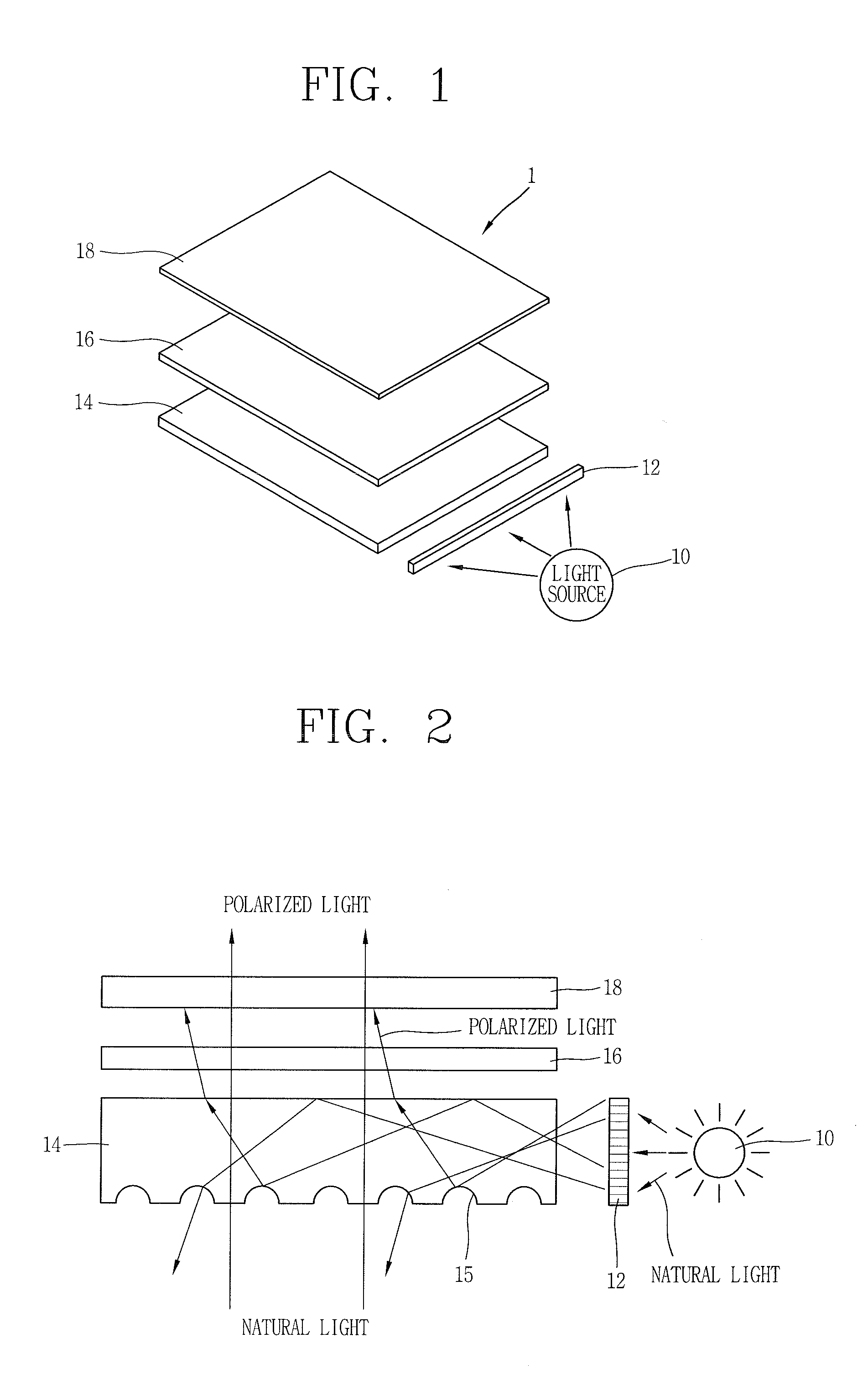
[0030]FIG. 1 is a view illustrating the structure of a transparent display device 1 according to the present invention.
[0031]As illustrated in FIG. 1, a transparent liquid crystal display device 1 according to a first embodiment of the present invention may include a liquid crystal display panel 16, a light guide plate 14 disposed at a lower portion of the liquid crystal display panel 16 to guide light to the liquid crystal display panel 16, a light source 10 disposed at a lateral surface of the light guide plate 14 to emit light to the light guide plate 14, a first polarizing plate 12 disposed between the light source 10 and a lateral surface of the light guide plate 14 to polarize the light emitted from the light source to enter into the light guide plate 14, and a second polarizing plate 18 disposed at an upper portion of the liquid crystal display panel 16 to polarize light passing through the liquid crystal display panel 16.
[0032]Though not shown in the drawing, the liquid crys...
second embodiment
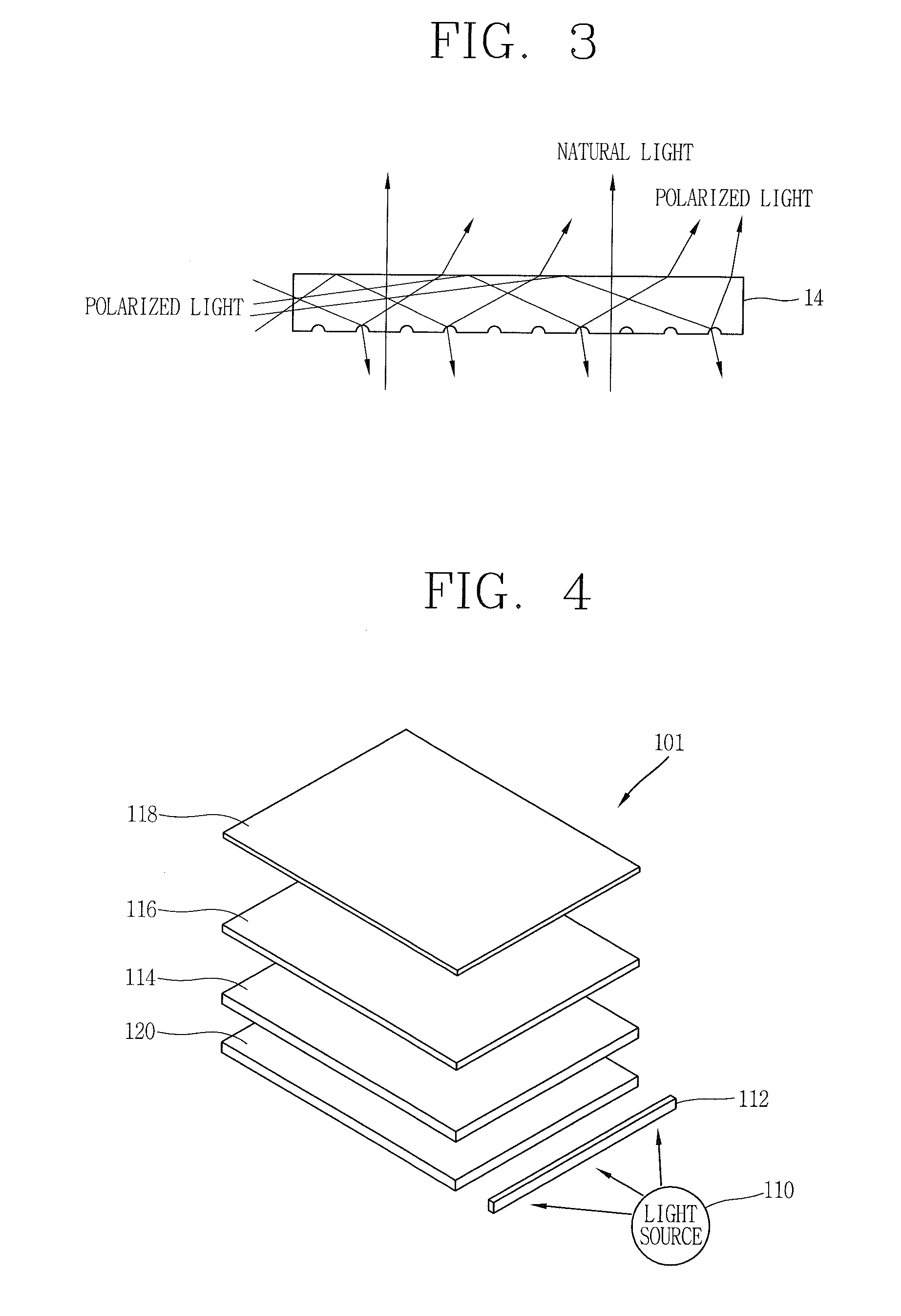
[0053]FIGS. 4 and 5 are views illustrating the structure of a transparent display device 101 according to the present invention, wherein FIG. 4 is an exploded perspective view and FIG. 5 is a front view.
[0054]As illustrated in FIGS. 4 and 5, a transparent display device 101 according to this embodiment may include a liquid crystal display panel 116, a light guide plate 114 disposed at a lower portion of the liquid crystal display panel 116 to guide light to the liquid crystal display panel 116, a light source 110 disposed at a lateral portion of the light guide plate 114 to emit light to the light guide plate 114, a first polarizing plate 112 disposed between the light source 110 and a lateral surface of the light guide plate 114 to polarize the light emitted from the light source to enter into the light guide plate 114, a second polarizing plate 118 disposed at an upper portion of the liquid crystal display panel 116 to polarize light passing through the liquid crystal display pane...
third embodiment
[0082]FIGS. 8a and 8b are views illustrating the structure of a transparent display device according to the present invention.
[0083]As illustrated in FIG. 8a, a transparent display device 201 according to this embodiment may include a liquid crystal display panel 216, a light guide plate 214 disposed at a lower portion of the liquid crystal display panel 216 to guide light to the liquid crystal display panel 216, a light source 210 disposed at a lateral portion of the light guide plate 214 to emit light to the light guide plate 214, a first polarizing plate 212 disposed between the light source 210 and a lateral surface of the light guide plate 214 to polarize the light emitted from the light source to enter into the light guide plate 214, a second polarizing plate 218 disposed at an upper portion of the liquid crystal display panel 216 to polarize light passing through the liquid crystal display panel 216, and an optical sheet 220 disposed at a lower portion of the liquid crystal d...
PUM
 Abstract
Description
Claims
Application Information