Display device and electrical apparatus

Active Publication Date: 2010-06-24
INNOLUX CORP
View PDF6 Cites 16 Cited by
  • Summary
  • Abstract
  • Description
  • Claims
  • Application Information

AI Technical Summary

Benefits of technology

[0009]Therefore, with the use of the display device and the electrical apparatus disclosed in the embodiments of the present

Problems solved by technology

However, the uneven structure of the above-mentioned display 900 may af

Method used


Image

  • Display device and electrical apparatus
  • Display device and electrical apparatus
  • Display device and electrical apparatus

Examples


Embodiment Construction

[0019]This description of the exemplary embodiments is intended to be read in connection with the accompanying drawings, which are to be considered part of the entire written description. In the description, relative terms such as “lower,”“upper,”“horizontal,”“vertical,”“above,”“below,”“up,”“down,”“top” and “bottom,” as well as derivative thereof (e.g., “horizontally,”“downwardly,”“upwardly,” etc.), should be construed to refer to the orientation as then described or as shown in the drawings under discussion. These relative terms are for convenience of description and do not require that the apparatus be constructed or operated in a particular orientation. In the drawings, like reference numerals correspondingly indicate like components or items.

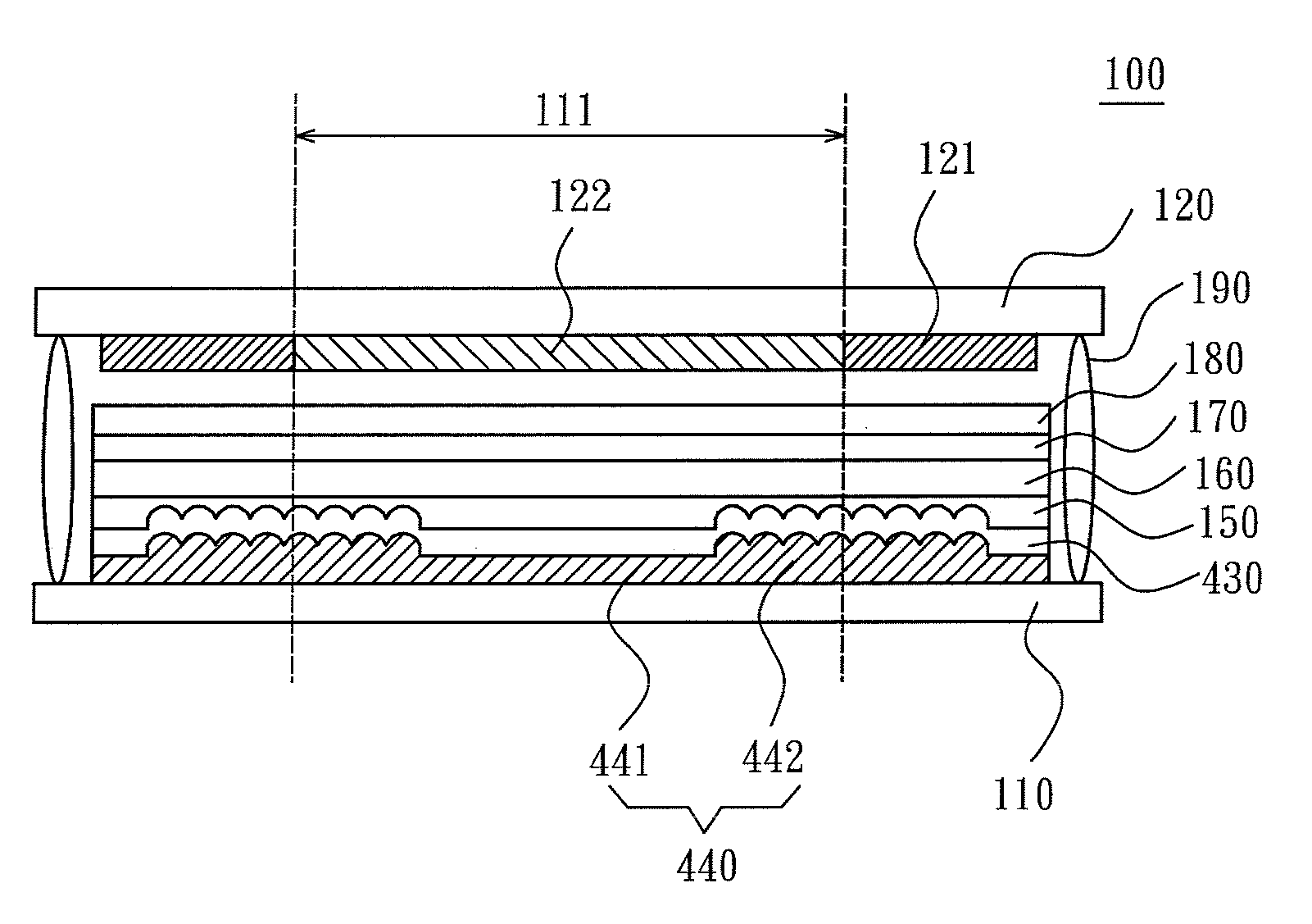
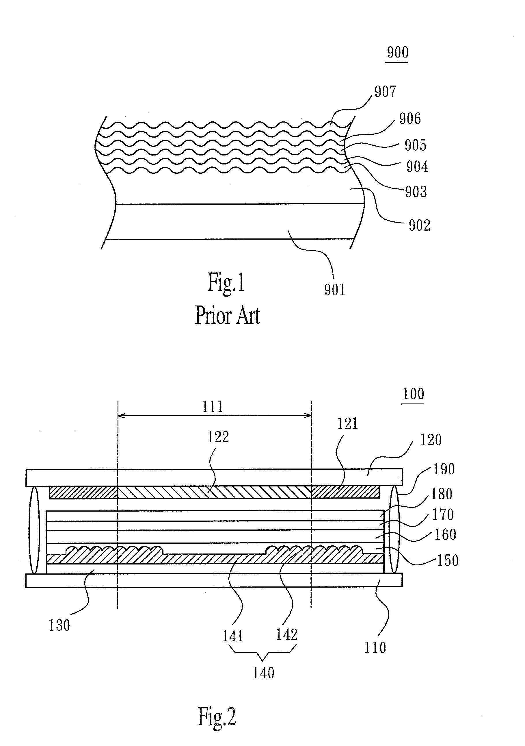
[0020]Please referring to FIG. 2, which is a partially cross-sectional view showing a display device according to a first embodiment of the present invention. The display device 100 of the present embodiment may be a self-emission type displ...


PUM


Abstract

A display device and an electrical apparatus are disclosed. The display device comprises a first substrate, an optical enhance layer, a display layer, a first electrode and a second electrode. The first substrate includes a plurality of pixel areas. The optical enhance layer is formed on the first substrate and includes a plurality of even structures and a plurality of uneven structures, wherein for each pixel area, one of the even structures corresponds to a portion of the pixel area, and one of the uneven structures corresponds to the rest portion of the pixel area. The first electrode is formed on the optical enhance layer. The display layer is formed on the first electrode. The second electrode is formed on the display layer. The display device is applicable to the electrical apparatus.

Description

CROSS REFERENCE TO RELATED APPLICATION[0001]The present application claims the benefit of the filing date under 35 U.S.C. §119(e) of a Provisional U.S. Patent Application No. 61 / 121,105, entitled “OLED with partially optical enhance structure”, filed on Dec. 9, 2008, which is incorporated by reference herein.FIELD OF THE INVENTION[0002]The present invention relates to a display device and an electrical apparatus, and more particularly, to a display device and an electrical apparatus including a plurality of partial uneven structures.BACKGROUND OF THE INVENTION[0003]Currently, with technological advantages, many types of display apparatus have been widely applied in flat panel displays (FPDs), such as liquid crystal displays (LCDs) or electro luminescence (EL) displays.[0004]Please refer to FIG. 1, which is a partially cross-sectional view showing a conventional display apparatus. Taking an EL display 900 for example, the EL display 900 includes a substrate 901, an insulating layer 9...

Claims


Application Information

Patent Timeline
IPC IPC(8): G02B5/22G02B7/00
CPCG02B3/0056G02B5/003G02B5/0263H01L51/5281G02B5/201H01L51/5262H01L51/5271G02B5/0858H10K50/85H10K50/856H10K50/86
Inventor SU, PO-KUNNISHIKAWA, RYUJI
Owner INNOLUX CORP
Why Eureka
Try Eureka