Image blur correction apparatus and image pickup unit having image blur correction apparatus

Active Publication Date: 2011-11-03
NIDEC COPAL CORPORATION
View PDF7 Cites 31 Cited by
  • Summary
  • Abstract
  • Description
  • Claims
  • Application Information

AI Technical Summary

Benefits of technology

[0039]According to the above-mentioned configured image blur correction apparatus, it is possible to obtain the image blur correction apparatus that can be mounted in a camera of, e.g., a mobile phone while achieving simplification of the structure, a reduction in size and thickness of the apparatus in the optical axis direction of t

Problems solved by technology

Further, although the second drive device drives the second movable member alone, the first drive device must drive not only the first movable member but also the second movable member and the second guide shaft together, and hence larger drive force must be generated as compared with a situation where the first movable member alone is driven, thereby resulting in an increase in size of the first drive device.
Furthermore, since a drive load of the first drive device is different from a drive load of the second drive device, drive control for positioning the lenses within a plane vertical to the optical axis is not easy.
Moreover, although the movable member is coupled with the base, since the fixed frame holding the coil is not integrally coupled, the image blur correction apparatus cannot be formed as a module, handling is inconvenient, the first magnet and the second magnet of the movable member and the first coil and the second coil of the fixed frame cannot be positioned with one member (e.g., the base) being determined as a reference, and h

Method used


Image

  • Image blur correction apparatus and image pickup unit having image blur correction apparatus
  • Image blur correction apparatus and image pickup unit having image blur correction apparatus
  • Image blur correction apparatus and image pickup unit having image blur correction apparatus

Examples


Embodiment Construction

[0078]Embodiments of the present invention will now be described hereinafter with reference to the accompanying drawings.

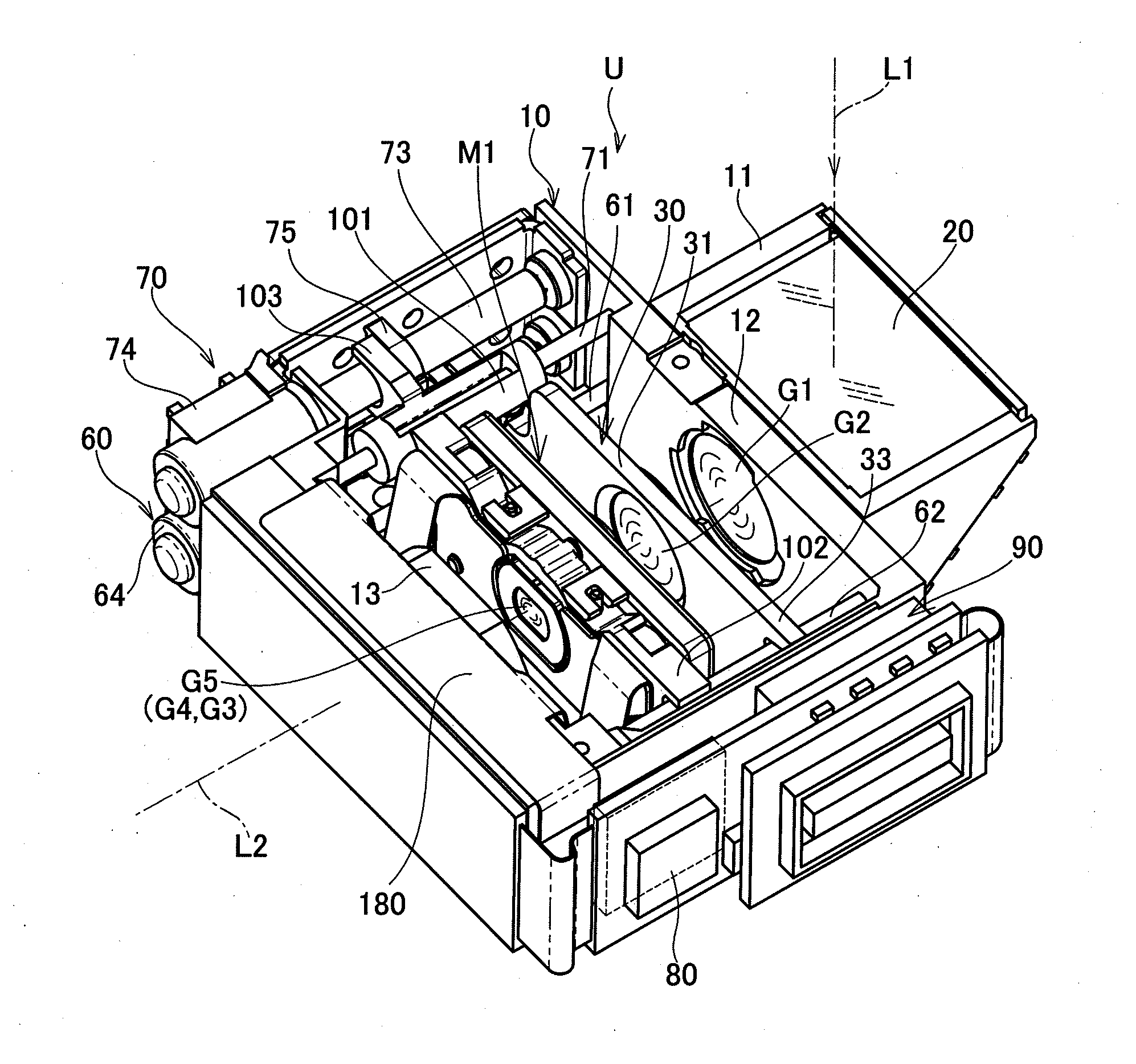
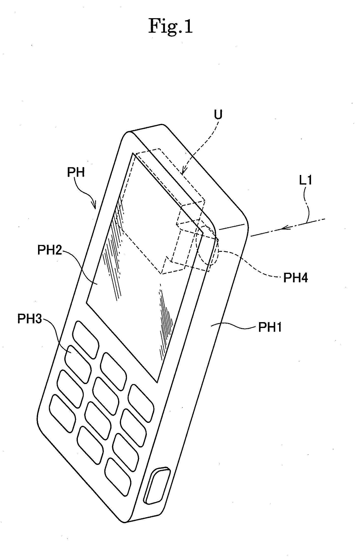
[0079]As shown in FIG. 1, an image pickup unit U having this image blur correction apparatus incorporated therein is mounted as a camera in a flat and small personal digital assistance PH. The personal digital assistance PH includes a housing PH1 having a substantially rectangular and flat outline, a display unit PH2 such as a liquid crystal panel that is arranged on a surface of the housing PH1 and configured to display various kinds of information, operation buttons PH3, an imaging window PH4 formed on a surface of the display unit PH2 on the opposite side, and others. Further, the image pickup unit U as a camera is accommodated in the housing PH1 in such a manner that this unit extends in a direction vertical to an optical axis L1 of subject light entering from the imaging window PH4 as shown in FIG. 1.

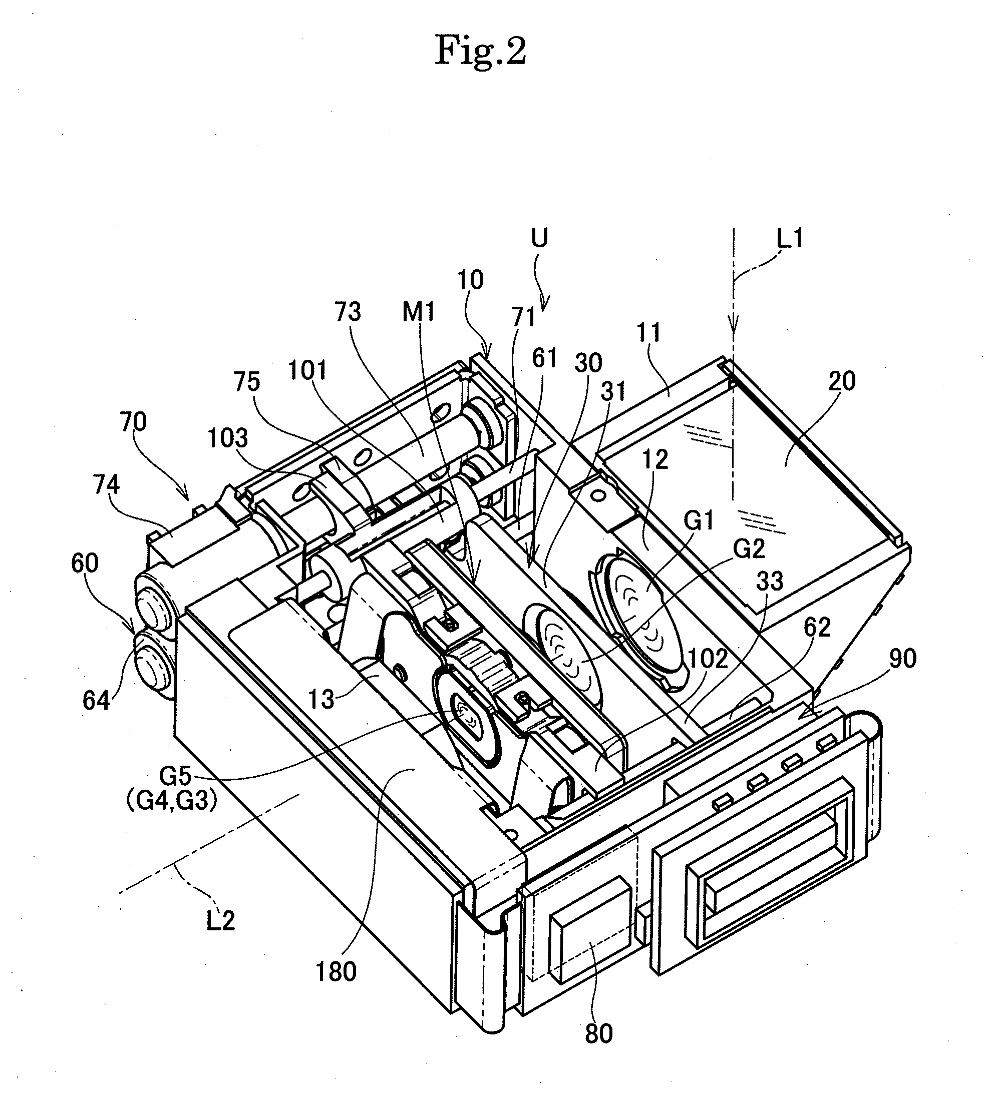
[0080]As shown in FIG. 2 and FIG. 3, the image pickup unit ...


PUM


Abstract

An image blur correction apparatus according to the present invention includes a base, a movable holding member, a support mechanism that supports the movable holding member to be movable within a plane vertical to an optical axis of a lens, a driving means for driving the movable holding member, a position detecting means, and a returning means for returning the movable holding member to a pause position, wherein the driving means includes coils (121, 131) fixed to the base and drive magnets (122, 132) fixed to the movable holding member, the returning means includes return magnets (161, 162) fixed to the base to face the drive magnets, the position detecting means includes magnetic sensors (171, 172) fixed to the base, and the support mechanism includes at least three concave portions (104) provided on the base, at least three spheres (150) rollably arranged in the concave portions, and at least three abutment surfaces (114) provided on the movable holding member to abut on the spheres. With this arrangement, the lens can be automatically centered while achieving simplification of the structure and miniaturization.

Description

TECHNICAL FIELD[0001]The present invention relates to an image blur correction apparatus (image stabilization device) mounted in, e.g., a lens body tube or a shutter unit of a digital camera and an image pickup unit having this image blur correction apparatus, and more particularly to a small and thin image blur correction apparatus applied to a camera mounted in a personal digital assistance such as a mobile phone and an image pickup unit having this image blur correction apparatus.BACKGROUND ART[0002]As a conventional image blur correction apparatus (image stabilization device), there is known an image blur correction apparatus including a substantially rectangular base having an opening portion at the center, a first guide shaft provided on a front surface of the base, a first movable member supported to be reciprocable along the first guide shaft, a second guide shaft that is directed to a 90-degree direction with respect to the first guide shaft and provided on a front surface ...

Claims


Application Information

Patent Timeline
IPC IPC(8): G02B27/64
CPCG03B5/02G03B17/02H04N1/00307H04N5/23248H04N5/23258H04N5/23287G02B27/648G02B13/001G02B13/0065G02B27/646G03B5/00G02B27/46H04N2007/145H04N23/68H04N23/6812H04N23/687
Inventor WATANABE, HIROYUKINAKAMURA, YUTA
Owner NIDEC COPAL CORPORATION
Why Eureka
Try Eureka