Maintenance apparatus having rotatable wiper and transfer rollers for printhead

Inactive Publication Date: 2011-11-17
ZAMTEC
View PDF11 Cites 2 Cited by
  • Summary
  • Abstract
  • Description
  • Claims
  • Application Information

AI Technical Summary

Benefits of technology

[0052]In another aspect the present invention provides a system for reducing ink color mixing effects in a printer, the system comprising:
[0074]Optionally, the each overflow port has a check valve so that back flow of ink from the connected overflow tubing is prevented.
[0089]Optionally, the each overflow port has a check valve so that back flow of ink from the connected overflow tubing is prevented.

Problems solved by technology

However, scanning printhead based printing systems are mechanically complex and slow in light of accurate control of the scanning motion and time delays from the incremental stopping and starting of the media with each scan.
Individual pressure regulators integrated into each printhead is unwieldy and expensive for multi-color printheads, particularly those carrying four or more inks.
Removing a depleted printhead can cause inadvertent spillage of residual ink if it has not been de-primed before decoupling from the printer.
Air bubbles trapped in printheads are a perennial problem and a common cause of print artifacts.
This is exacerbated by large arrays of nozzles as more ink is lost as the number of nozzles increases.
Further, such media width printheads having a large array of inkjet nozzles are difficult to maintain.
For example, there is a need to maintain the printheads which becomes exceptionally difficult when the array of nozzles is as long as the media is wide.
However, when a printhead is returned to its operative position its alignment for correct printing is prone to drift until eventually visible artifacts demand hardware and / or software mechanisms to realign the printhead.
Both of these system designs suffer from drawbacks of large printer width dimensions, complicated design and control, and difficulty in maintaining printhead alignment.
Further, these systems add size to the printer.
Further, the high media transport speeds used in such media width printers, particularly those which print on continuous web media, have typically lead to more complex media transport systems in the printers, due to the need to minimize media feed errors.

Method used


Image

  • Maintenance apparatus having rotatable wiper and transfer rollers for printhead
  • Maintenance apparatus having rotatable wiper and transfer rollers for printhead
  • Maintenance apparatus having rotatable wiper and transfer rollers for printhead

Examples


Embodiment Construction

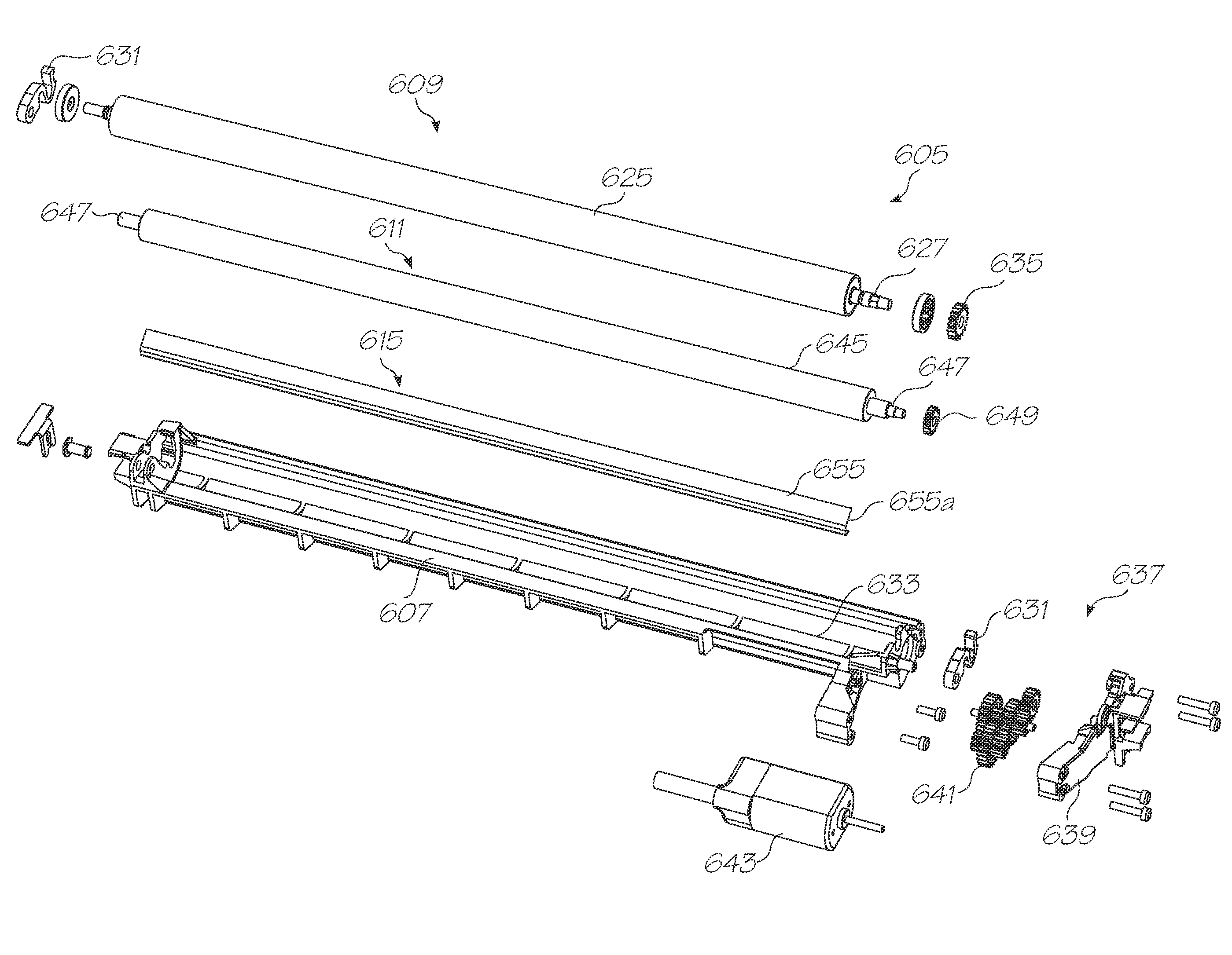
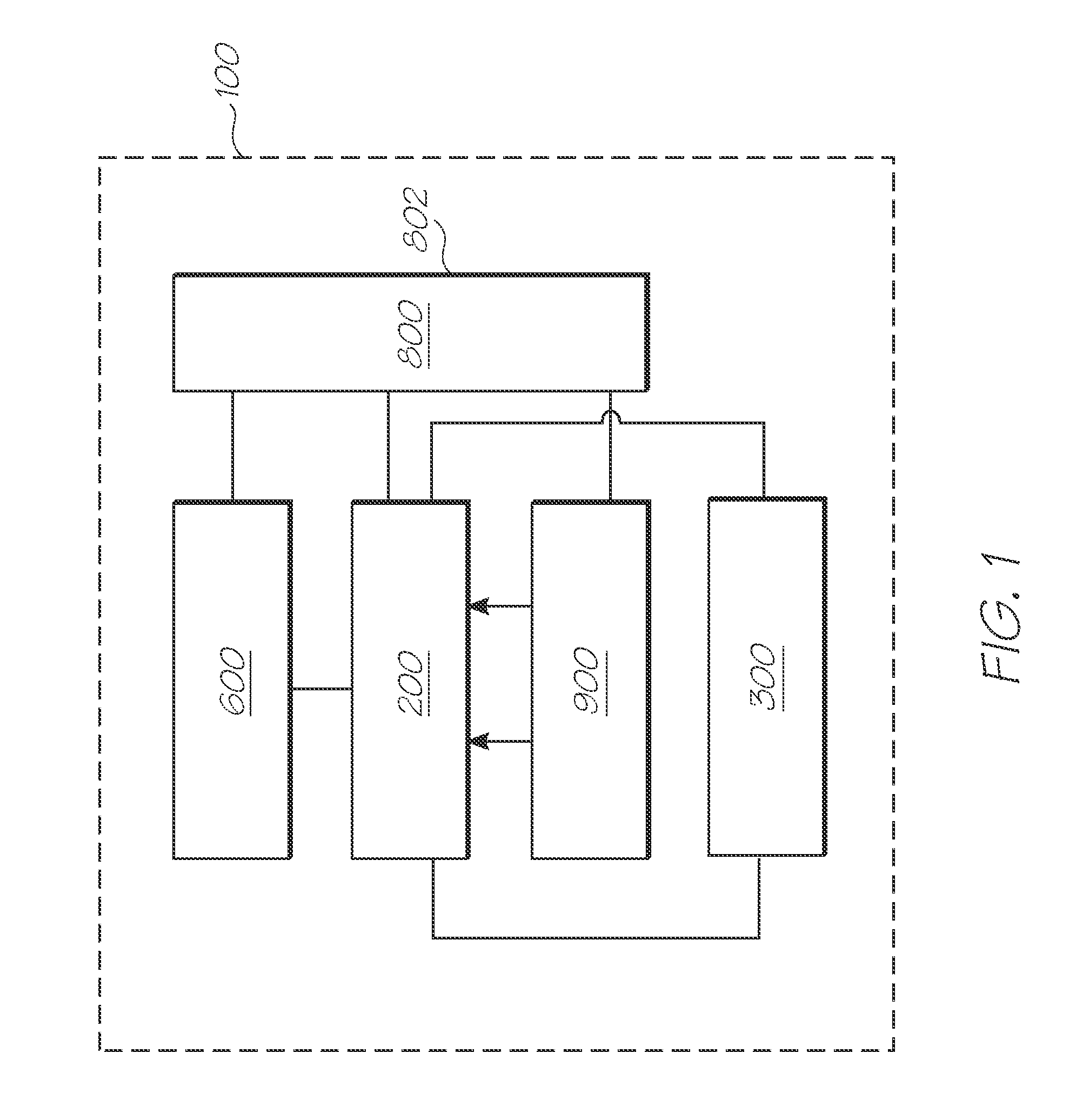
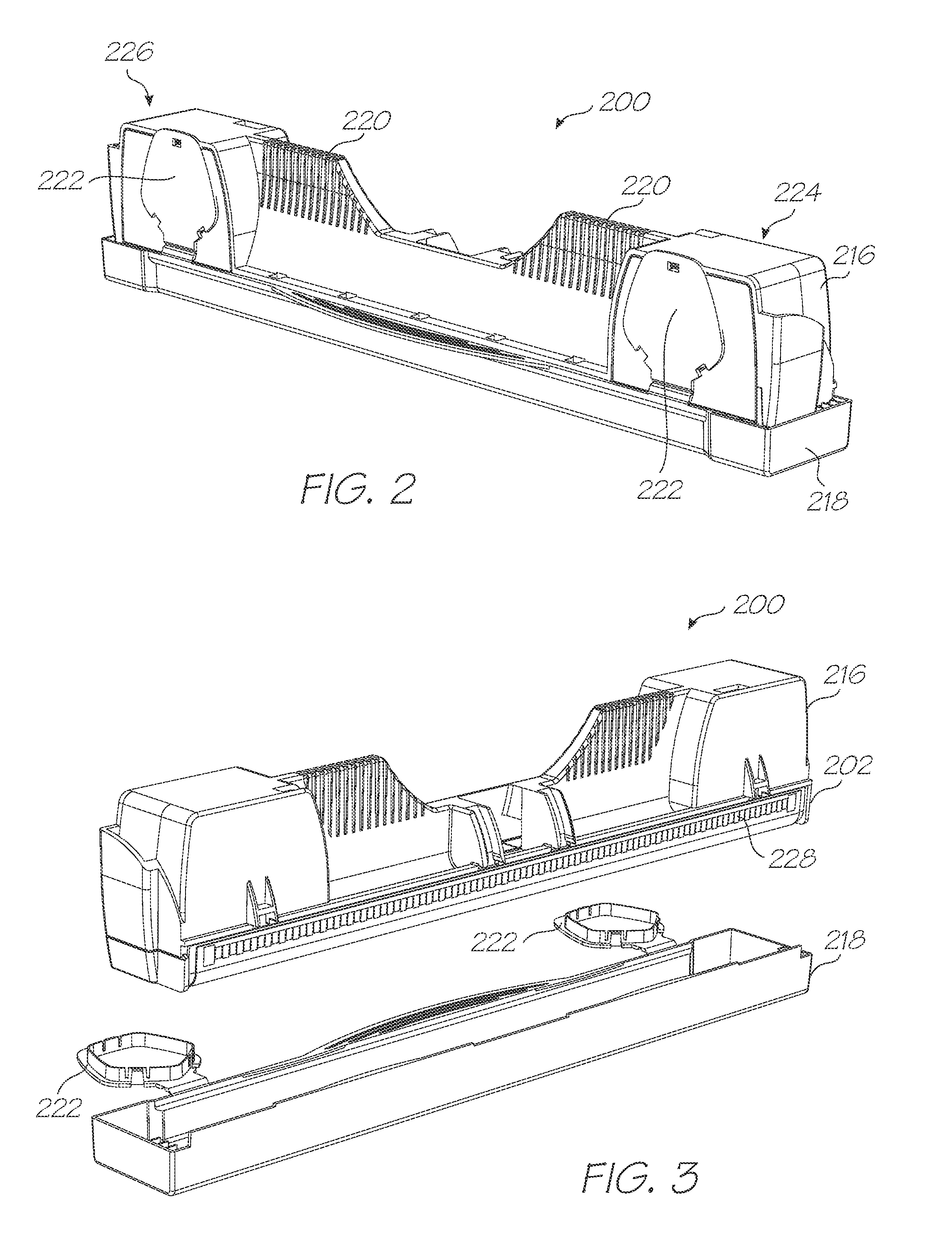
[0314]An exemplary block diagram of the main system components of a printer 100 is illustrated in FIG. 1. The printer 100 has a printhead 200, fluid distribution system 300, maintenance system 600, electronics 800 and media handling system 900.

[0315]The printhead 200 has fluid ejection nozzles for ejecting printing fluid, such as ink, onto passing print media. The fluid distribution system 300 distributes ink and other fluids for ejection by the nozzles of the printhead 200. The maintenance system 600 maintains the printhead 200 so that reliable and accurate fluid ejection is provided from the ejection nozzles. The media handling system 900 provides transport and guidance of media past the printhead 200 for printing.

[0316]The electronics 800 operatively interconnects the electrical components of the printer 100 to one another and to external components / systems. The electronics 800 has control electronics 802 for controlling operation of the connected components. An exemplary configu...


PUM


Abstract

An apparatus for maintaining a printhead is provided having a rotatable wiper roller having a shaft and a porous material about the shaft, a rotatable transfer roller in rotatable contact with the wiper roller, and a mechanism for rotating the wiper roller so that the porous material rotates against the printhead such that the porous material absorbs fluid from the printhead during the rotation, and for rotating the transfer roller against the wiper roller so that the fluid absorbed by the porous material is transferred to the transfer roller.

Description

FIELD OF INVENTION[0001]The invention relates to printing systems, printing apparatus and methods for printing on continuous web media, and in particular continuous label web media, and to the configuration and arrangement of the components of such systems and apparatus. The related printing systems, apparatus and methods include those which distribute fluid within a printing environment. In particular, the fluid is a printing fluid, such as ink or ink fixing agent, as is distributed to and from a fluid ejection printhead, such as an inkjet printhead. More particularly, fluid distribution to an inkjet media width printhead is provided. The related printing systems, apparatus and methods also include those which maintain such a printhead and which handle the media before and after the media is printed on by the printhead.CO-PENDING APPLICATIONS[0002]The following applications have been filed by the Applicant which relate to the present application:KPF001USKPF002USKPF003USKPF004USKPF0...

Claims


Application Information

Patent Timeline
IPC IPC(8): B41J2/165
CPCB41J2/19B41J2/16585B41J2/16535B41J2/16541B41J2/175B41J2/17556B41J2/1752B41J2/17553B41J2/18B41J2202/02
Inventor LOVE, JOHN CHRISTIANLUESCHEN, JEFFREY D.FISHBEIN, PAULSEITER, PAULWILLIAMS, GREG
Owner ZAMTEC
Why Eureka
Try Eureka