
Film for in-molding, in-mold molded product, and method for manufacturing in-mold molded product

Active Publication Date: 2017-07-20
PANASONIC INTELLECTUAL PROPERTY MANAGEMENT CO LTD
View PDF2 Cites 3 Cited by
  • Summary
  • Abstract
  • Description
  • Claims
  • Application Information

AI Technical Summary

Benefits of technology

The invention prevents ink from flowing into the coloring layer, which helps avoid defects in the final product. This is achieved by using a special arrangement of layers between the inorganic polymers.

Problems solved by technology

Even in such an environment, in-mold molded products are not sufficiently used in the interior of vehicles.
This is because that high-strength polycarbonate or the like is used as a resin of the interior of vehicles, but a film for in-molding capable of sufficiently withstanding a molding temperature thereof is not provided and defects of appearance occur in a process of manufacturing a molded product.
In addition to the interior of vehicles, polycarbonate or the like is also used as a resin for molding in the exterior of vehicles or the exterior of smart phones, and the same problems described above occur.

Method used


Image

  • Film for in-molding, in-mold molded product, and method for manufacturing in-mold molded product
  • Film for in-molding, in-mold molded product, and method for manufacturing in-mold molded product
  • Film for in-molding, in-mold molded product, and method for manufacturing in-mold molded product

Examples


exemplary embodiment 1

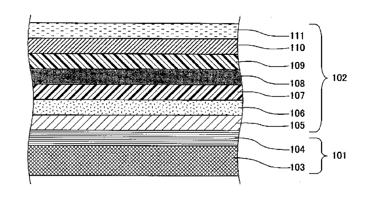
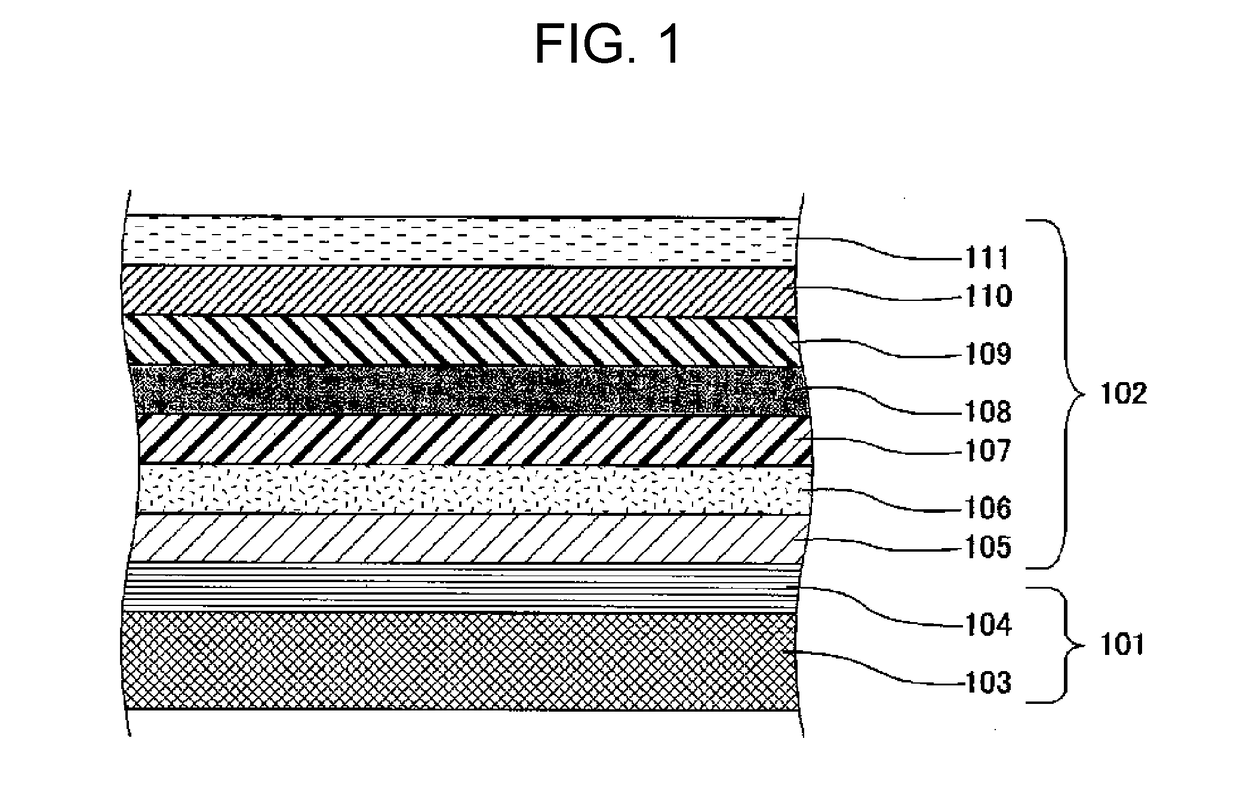
[0029]FIG. 1 shows a layer configuration of a film for in-molding of Exemplary Embodiment 1 of the invention. As shown in FIG. 1, the film for in-molding of this exemplary embodiment is a continuous film configured with carrier film 101 and transfer film 102.

[0030]Carrier film 101 is a portion of the film for in-molding which is not transferred to an injection molding resin and is configured with base film 103 and peeling layer 104. Base film 103 has a function of continuously supplying transfer film 102. Peeling layer 104 is used for peeling transfer film 102 from base film 103.

[0031]Transfer film 102 is a portion of the film for in-molding which is transferred to an injection molding resin. Transfer film 102 is generally configured to have a film thickness of 2 μm to 50 μm inclusive. Transfer film 102 is, for example, configured with protective layer or hard coat layer 105, primer layer 106, first inorganic polymer layer 107, coloring layer 108, second inorganic polymer layer 109,...

exemplary embodiment 2

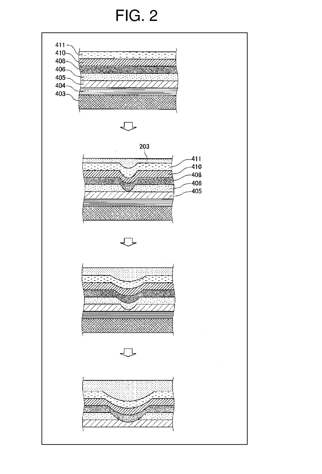
[0051]FIG. 5 is an enlarged sectional view of a film for in-molding of Exemplary Embodiment 2 of the invention and is a view obtained by further enlarging a part of the enlarged sectional view. The same reference numerals are used for the same constituent elements shown in FIG. 1 and the description thereof will be omitted. A film for in-molding of Exemplary Embodiment 2 of the invention includes porous fillers 301 in first inorganic polymer layer 107 and second inorganic polymer layer 109 interposing coloring layer 108. When a film for in-molding having this configuration is manufactured, a film for in-molding in which a gate flow hardly occurs even when an injection resin is used at a higher temperature is provided. Other configurations are the same as those in Exemplary Embodiment 1 and therefore, the description thereof will be omitted.

[0052]In the film for in-molding of Exemplary Embodiment 2, since first inorganic polymer layer 107 and second inorganic polymer layer 109 includ...


PUM

PropertyMeasurementUnit
Percent by massaaaaaaaaaa
Thicknessaaaaaaaaaa

Abstract

A film for in-molding is configured with a transfer film which is transferred to a surface of an injection molding resin, and a carrier film which is not transferred. The transfer film includes a coloring layer which includes ink which is an organic material formed of a thermoplastic resin and applies a design to an in-mold molded product, and inorganic polymer layers formed of a thermosetting resin, and the coloring layer comes into contact with the inorganic polymer layers and is interposed between the inorganic polymer layers.

Description

TECHNICAL FIELD[0001]The present invention relates to a film for in-molding, an in-mold molded product, and a method for manufacturing the same. The invention more specifically relates to a highly heat-resistant film for in-molding capable of withstanding high temperature at the time of resin molding, an in-mold molded product obtained using the highly heat-resistant film for in-molding, and a method for manufacturing the same.BACKGROUND ART[0002]In recent years, technologies relating to vehicles generally used have rapidly changed. For aiming environmental consideration and high efficiency of an engine, a fuel has been developed from gasoline to hybrid, fuel cells, and hydrogen batteries. A large number of resin molded products is used in the interior of vehicles, in order to reduce a weight, and the development of interior decoration of vehicles has been proceeded in accordance with the usage of the resin molded products to change the interior of the vehicles into a comfortable sp...

Claims


Application Information

Patent Timeline
IPC IPC(8): B44C1/17B32B27/00B29C45/14B32B3/08
CPCB44C1/1704B32B3/08B32B27/00B29C45/14827B29C45/1418B29C2045/14713B29C45/14688B32B2451/00B32B2605/003B29L2031/722B29L2031/30B29C45/14336B44C1/1716B29C45/14811B29C45/14836B29K2105/16B29K2709/00B29K2995/002B29K2995/007
Inventor SHIBATA, GAKUEIKANEUCHI, KAZUHIKO
Owner PANASONIC INTELLECTUAL PROPERTY MANAGEMENT CO LTD
Learn More