Pedal apparatus

a technology of pedals and cylinders, applied in the direction of mechanical control devices, process and machine control, instruments, etc., can solve the problems of sudden increase of increased output voltage of sensors, and increased discomfort of drivers (adjustment, acceleration, etc., to achieve the effect of improving the operational feeling

Inactive Publication Date: 2012-01-12
DENSO CORP +1
View PDF3 Cites 8 Cited by
  • Summary
  • Abstract
  • Description
  • Claims
  • Application Information

AI Technical Summary

Benefits of technology

[0007]The present invention is made in view of the above disadvantages. Thus, it is an objective of the present invention to provide a pedal apparatus, which implements an improved operational feeling to a user at the time of starting depression of a pedal member.

Problems solved by technology

Therefore, the output voltage of the sensor is instantaneously increased, and the driver may experience an uncomfortable feeling of abrupt starting (or an uncomfortable feeling of abrupt acceleration) of the vehicle.
However, with this construction, when the contact position of the friction washer relative to a pedal rotor or a spring rotor is changed due to a physical change of the friction washer caused by a long term use (or aging) or temperature change, the hysteric characteristics may possibly be varied.

Method used


Image

  • Pedal apparatus
  • Pedal apparatus
  • Pedal apparatus

Examples


first embodiment

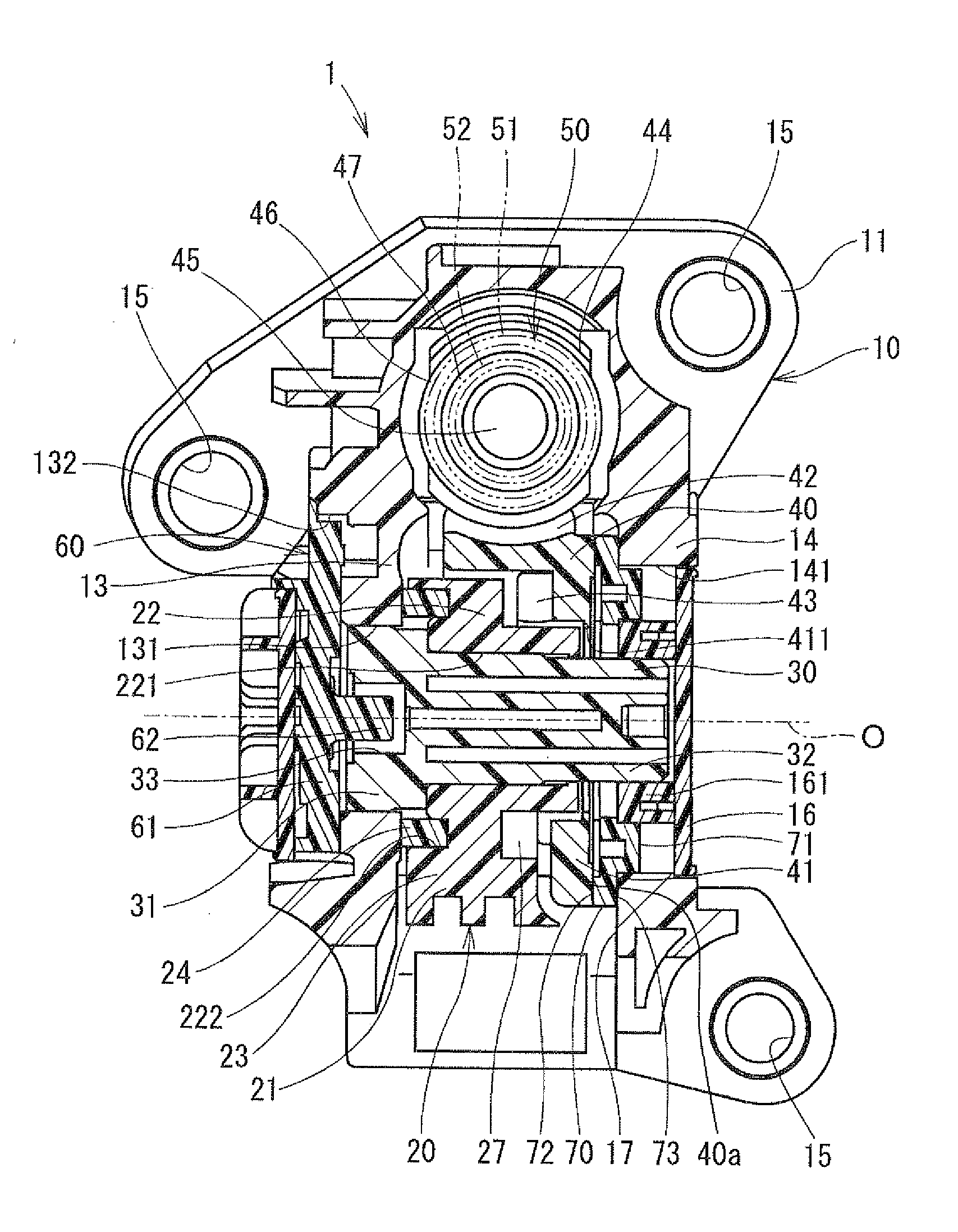
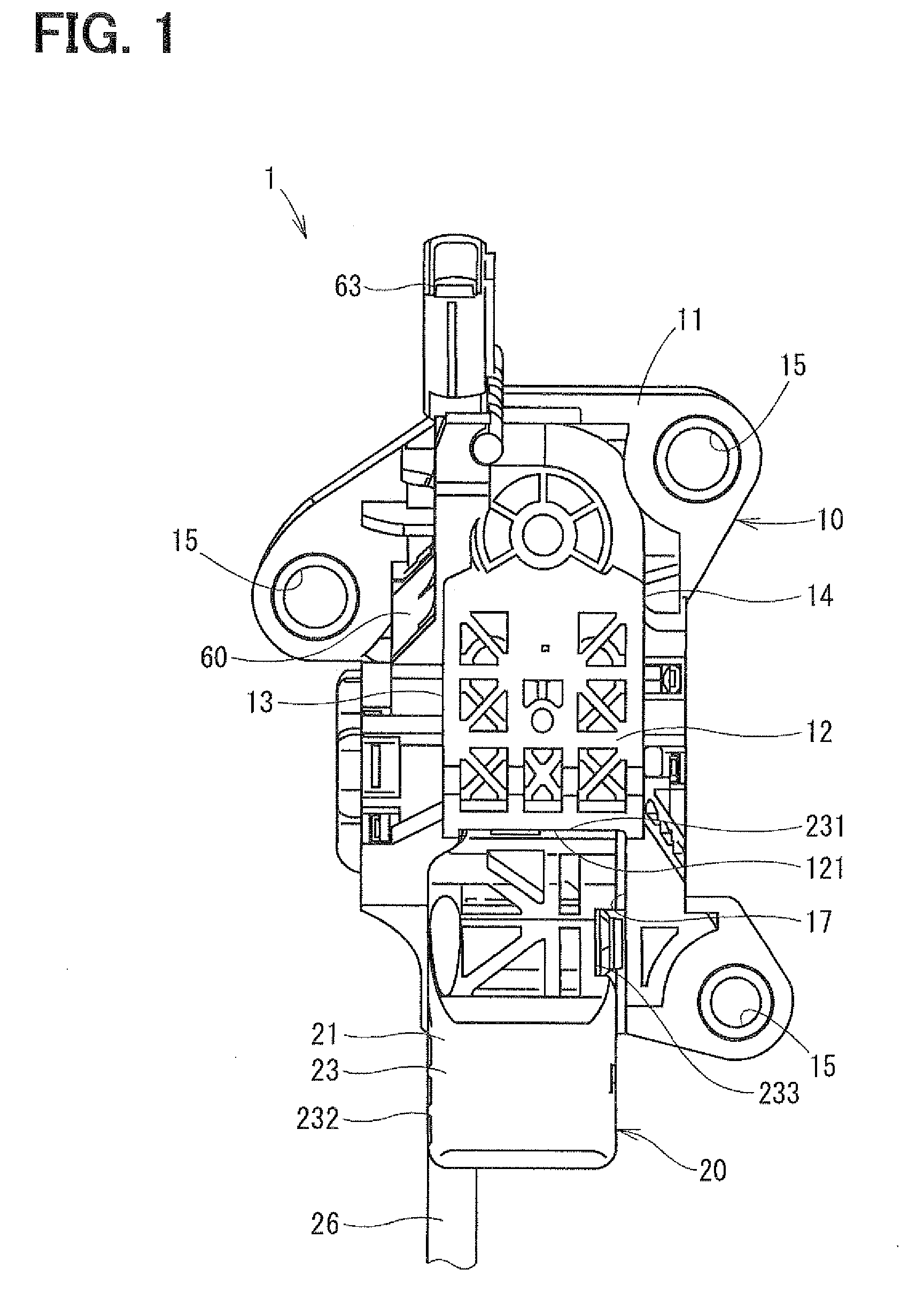
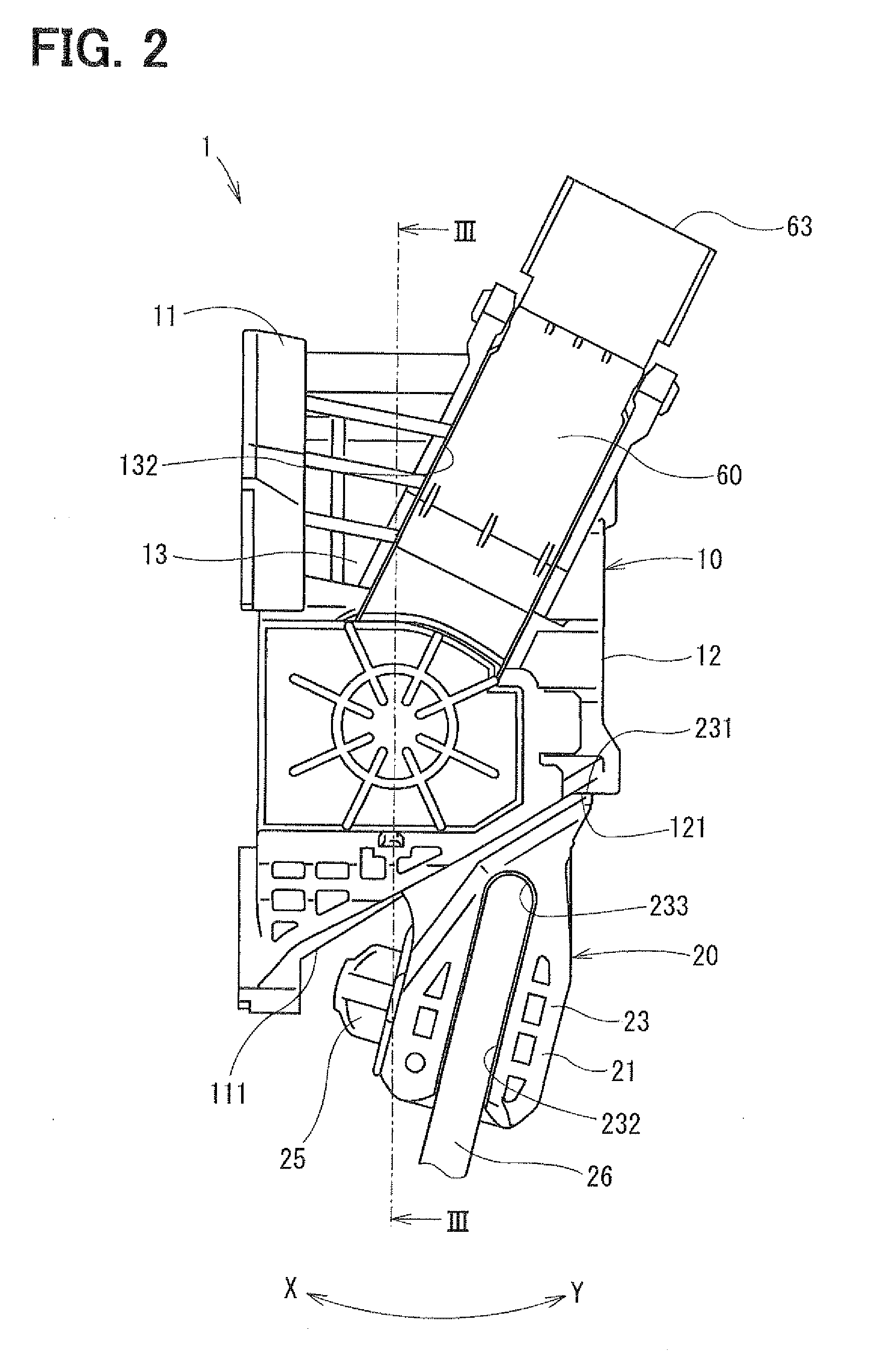
[0031]A pedal apparatus according to a first embodiment of the present invention will be described with reference to FIGS. 1 to 7. In the present embodiment, the pedal apparatus is formed as an accelerator pedal apparatus that is installed to a vehicle (e.g., an automobile) and controls a driving state of the vehicle in response to the amount of depression of a pedal member of the pedal apparatus, which is depressed by a foot of a driver of the vehicle. The pedal apparatus is of a drive-by-wire type. A signal, which indicates a rotational angle of the pedal member sensed with a rotational angle sensor, is transmitted to an engine control unit (ECU), which in turn controls a throttle apparatus based on the sensed rotational angle of the pedal member.

[0032]As shown in FIGS. 1 to 3, the pedal apparatus 1 includes a housing (serving as a support member) 10, the pedal member 20, a double coil spring (serving as an urging means or an urging device) 50, the rotational angle sensor 60 and a...

second embodiment

[0094]A friction washer used in the pedal apparatus according to a second embodiment of the present invention will be described with reference to FIGS. 8 to 11. In the following embodiments, the components, which are similar to those of the first embodiment, will be indicated by the same reference numerals and will not be described to avoid redundancy. Furthermore, since the remaining components of the pedal apparatus, which are other than the friction washer, are substantially the same as those of the first embodiment, these remaining components shown in FIGS. 1 to 3 will be also referred with the same reference numerals.

[0095]The friction washer (serving as a friction means or a friction device) 80 of the second embodiment is configured into a generally planar arcuate disk and is placed between the side plate 14 of the housing 10 and the spring rotor 40, and a plane of the friction washer 80 is generally perpendicular to the rotational axis O. The friction washer 80 generates the ...

third embodiment

[0102]A friction washer used in the pedal apparatus according to a third embodiment of the present invention will be described with reference to FIGS. 12 to 16. The present embodiment is a modification of the second embodiment, and a friction washer (serving as a friction means or a friction device) 90 of the present embodiment is configured into a generally planar arcuate disk and is placed between the spring rotor 40 and the side plate 14 of the housing 10, and a plane of the friction washer 90 is generally perpendicular to the rotational axis O. The friction washer 90 exerts the frictional force against the rotational movement of the pedal member 20.

[0103]The friction washer 90 includes a fixing portion 94, a resiliently deformable portion 95, slidable contact portions 92 and engaging portions 93 and is integrally molded, i.e., integrally formed from a resin material as a single piece. A dotted line 86 in FIG. 12 illustratively indicates a boundary between the fixing portion 94 a...


PUM


Abstract

A friction washer (70, 80, 90) is placed between a housing (10) and a pedal member (20) and exerts a frictional force against rotational movement of the pedal member (20). The friction washer (70, 80, 90) includes at least one displaceable portion (72, 75, 82, 85, 92, 95), which is adapted to be displaced relative to the rest of the friction washer (70, 80, 90) by a predetermined amount in a circumferential direction about a rotational axis (O) of the pedal member (20) upon rotation of the pedal member (20).

Description

CROSS REFERENCE TO RELATED APPLICATION[0001]This application is based on and incorporates herein by reference Japanese Patent Application No. 2009-57742 filed on Mar. 11, 2009.TECHNICAL FIELD[0002]The present invention relates to a pedal apparatus for a vehicle.BACKGROUND ART[0003]For instance, in a known accelerator pedal apparatus installed to a vehicle, a pedal member is rotated in a depressing direction by a pedal force, which is a force applied from a foot of a driver (user) against the pedal member. When the pedal force applied against the pedal member is released, the pedal member is rotated in a releasing direction, which is opposite from the depressing direction, by a resilient force of a spring that urges the pedal member in the releasing direction. A rotational angle of the pedal member is sensed with a rotational angle sensor, and a signal, which indicates the sensed rotational angle, is sent from the sensor to an engine control unit (ECU) of an internal combustion engin...

Claims


Application Information

Patent Timeline
Patent Type & Authority Applications(United States)
IPC IPC(8): G05G1/30
CPCG05G1/38Y10T74/20534G05G5/03
Inventor HOTTA, KEISUKESUZUKI, HARUHIKOWATANABE, HIDEKAZUNEBUYA, HIDETOTERAKADO, TOSHIICHIMAEHARA, KAZUTAKASAKURABA, TOMOHIRO
Owner DENSO CORP
Why Eureka
Try Eureka