Imaging apparatus, imaging system, and method for controlling imaging apparatus

a technology of imaging apparatus and imaging system, which is applied in the direction of exposure control, printing, instruments, etc., can solve the problem that the method cannot meet the demand for and achieve the effect of reducing the exposure preparation period

Inactive Publication Date: 2012-03-29
CANON KK
View PDF4 Cites 9 Cited by
  • Summary
  • Abstract
  • Description
  • Claims
  • Application Information

AI Technical Summary

Benefits of technology

[0011]The present invention is directed to an imaging apparatus and an imaging system capable of reducing the exposure preparation period and performing a suitable offset correction for the variation in the offset.

Problems solved by technology

The offset (dark current) causes a problem due to the following reason in the detector using a photoelectric conversion element.
On the other hand, the method discussed in U.S. Pat. No. 6,448,561 cannot perform imaging until the offset stabilizes after the bias is applied to the photoelectric conversion element, so that the method cannot meet a demand for reducing the exposure preparation period.

Method used


Image

  • Imaging apparatus, imaging system, and method for controlling imaging apparatus
  • Imaging apparatus, imaging system, and method for controlling imaging apparatus
  • Imaging apparatus, imaging system, and method for controlling imaging apparatus

Examples


Embodiment Construction

[0029]Various exemplary embodiments, features, and aspects of the invention will be described in detail below with reference to the drawings.

[0030]A radiation in the present invention includes not only α ray, β ray, γ ray which are beams made of particles (including photons) emitted by radioactive decay, but also beams whose energy is comparable thereto, for example, X ray, particle beam, and cosmic radiation.

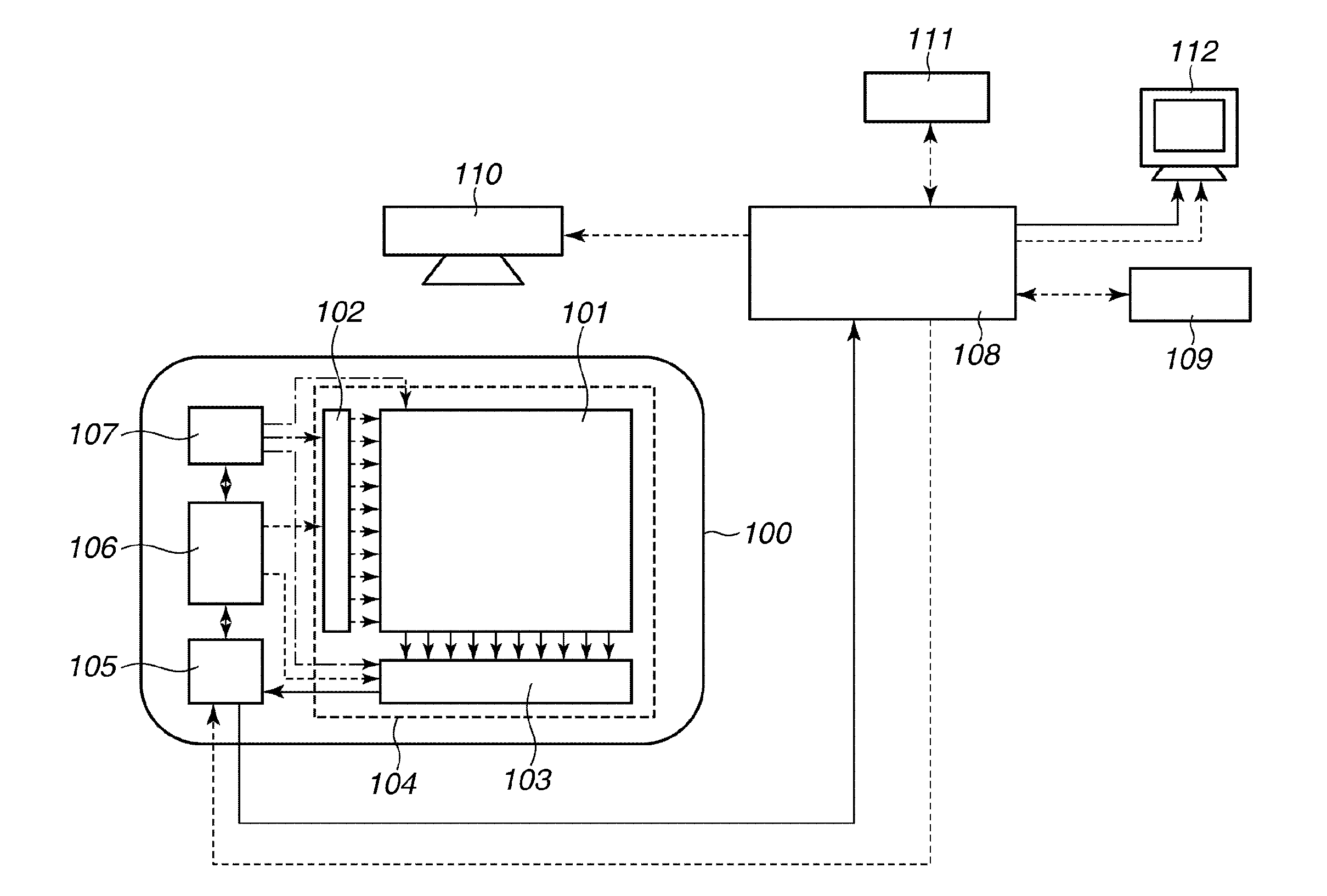
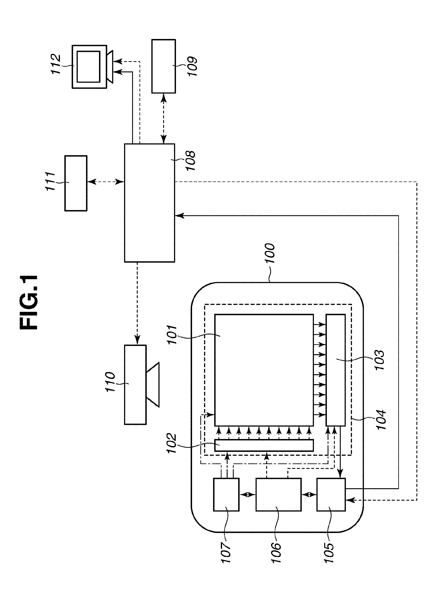
[0031]The imaging system of the present exemplary embodiment illustrated in FIG. 1 includes an imaging apparatus 100, a control computer 108, a imaging condition memory 109, a radiation generating apparatus 110, a console 111, and a display apparatus 112.

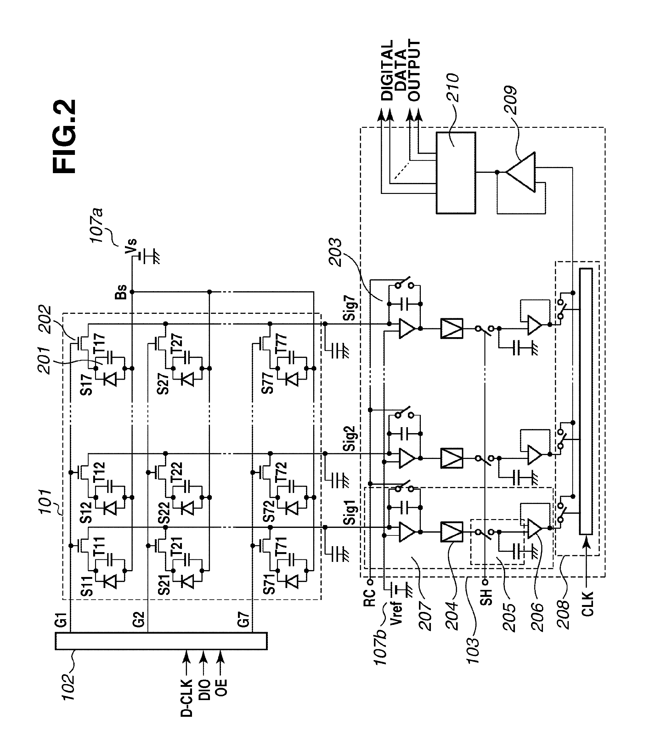
[0032]The imaging apparatus 100 includes a flat panel detector (FPD) 104 including a detection unit 101 provided with a plurality of pixels which convert radiation or light into an electric signal, a drive circuit 102 which drives the detection unit 101, and a read circuit 103 which outputs the electric signal output from the d...


PUM


Abstract

An imaging apparatus includes a detector in which a plurality of pixels are arranged in a matrix; each pixel includes a conversion element that converts radiation or light into an electric charge. The detector performs an exposure imaging operation for outputting exposure image data, a correction imaging operation for outputting correction image data, and a correction imaging preparation operation including an initialization operation for initializing the conversion element between the exposure imaging operation and the correction imaging operation. A correction unit corrects the exposure image data using the correction image data; and a control unit controls the operation of the detector so that the detector performs the initialization operation based on an amount of variation in offset of the conversion element at the time of transitioning from an exposure imaging preparation operation to the exposure imaging operation.

Description

BACKGROUND OF THE INVENTION[0001]1. Field of the Invention[0002]The present invention relates to an imaging apparatus, an imaging system, and a method for controlling the imaging apparatus. More specifically, the present invention relates to an imaging apparatus used for a radiation imaging apparatus and a radiation imaging system which are preferably used for still imaging such as general imaging in medical diagnosis and moving imaging such as X-ray radioscopic imaging and a method for controlling the imaging apparatus.[0003]2. Description of the Related Art[0004]In recent years, a radiation imaging apparatus using a flat panel detector (FPD) formed of a semiconductor material has been put into practical use as an imaging apparatus used for an X-ray medical image diagnosis and an X-ray nondestructive inspection. Such a radiation imaging apparatus has been used as a digital imaging apparatus for the still imaging such as general imaging and for moving imaging such as X-ray radioscop...

Claims


Application Information

Patent Timeline
Patent Type & Authority Applications(United States)
IPC IPC(8): G03B27/02
CPCG03B42/02G03B7/08
Inventor SATO, SHOENDO, TADAOKAMESHIMA, TOSHIOYAGI, TOMOYUKITAKENAKA, KATSUROYOKOYAMA, KEIGOIWASHITA, ATSUSHI
Owner CANON KK
Why Eureka
Try Eureka