Illumination device and projection type display device using the same

Inactive Publication Date: 2012-09-06
SHARP NEC DISPLAY SOLUTIONS LTD
View PDF2 Cites 15 Cited by
  • Summary
  • Abstract
  • Description
  • Claims
  • Application Information

AI Technical Summary

Benefits of technology

[0024]An object of the present invention is to provide a small illumination device and projection type display device that uses the ill

Problems solved by technology

Thus, a light loss occurs on the surface of the LED, thus preventing realization of high polarizing conversion efficiency.
Since the illumination device presented in Patent Literature 3 uses a PBS polarizati

Method used


Image

  • Illumination device and projection type display device using the same
  • Illumination device and projection type display device using the same
  • Illumination device and projection type display device using the same

Examples


first exemplary embodiment

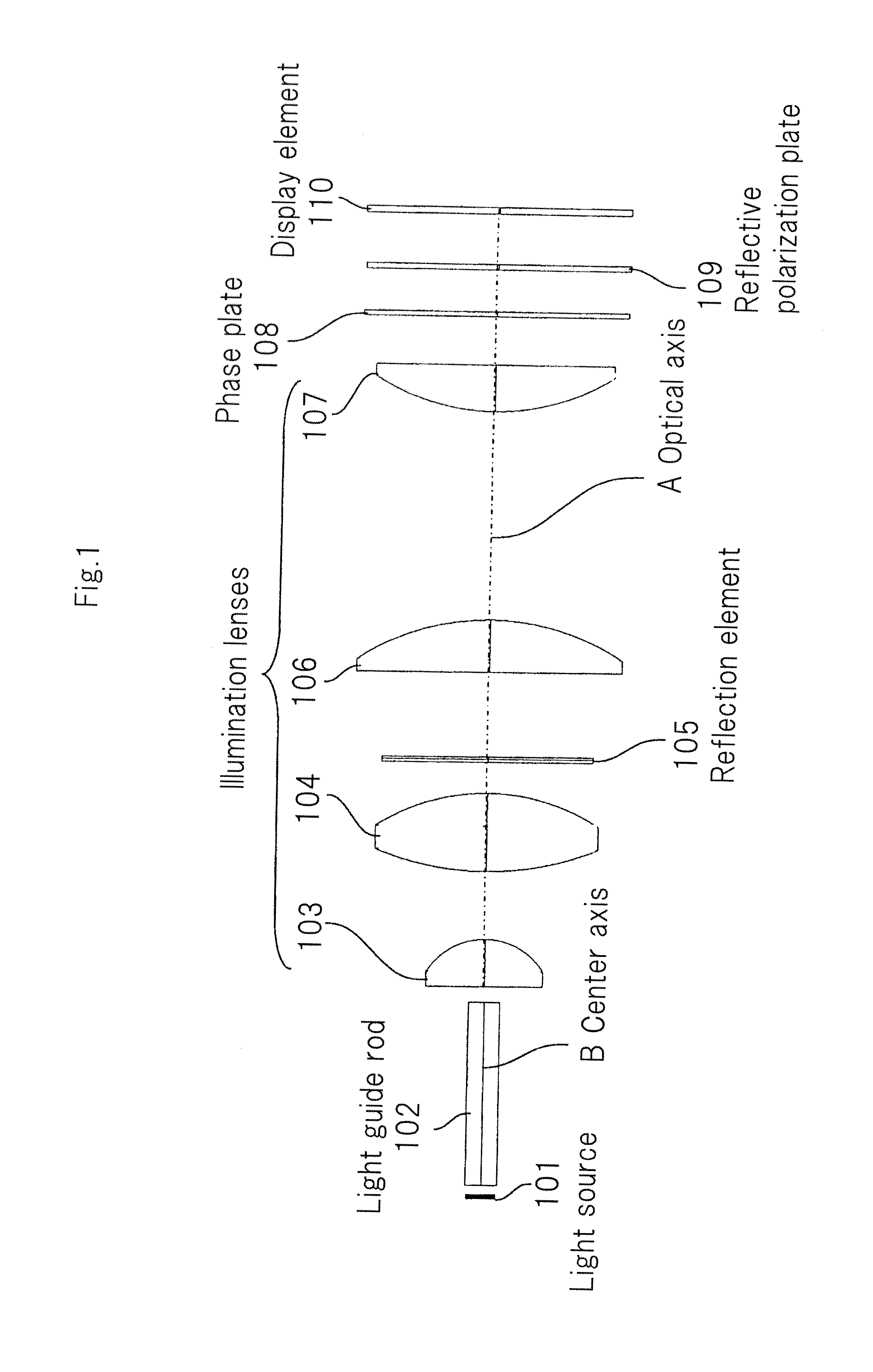
[0074]FIG. 1 is a schematic diagram showing the structure of illumination device according to an exemplary embodiment of the present invention.

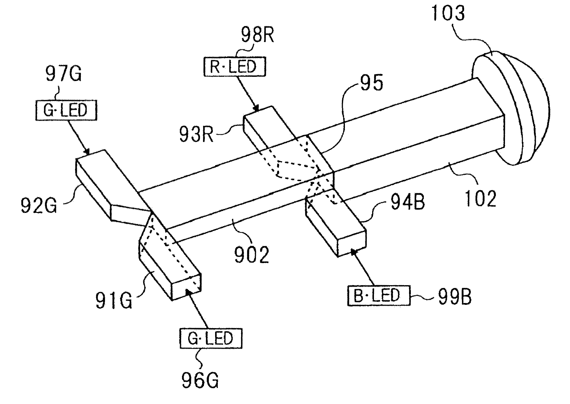
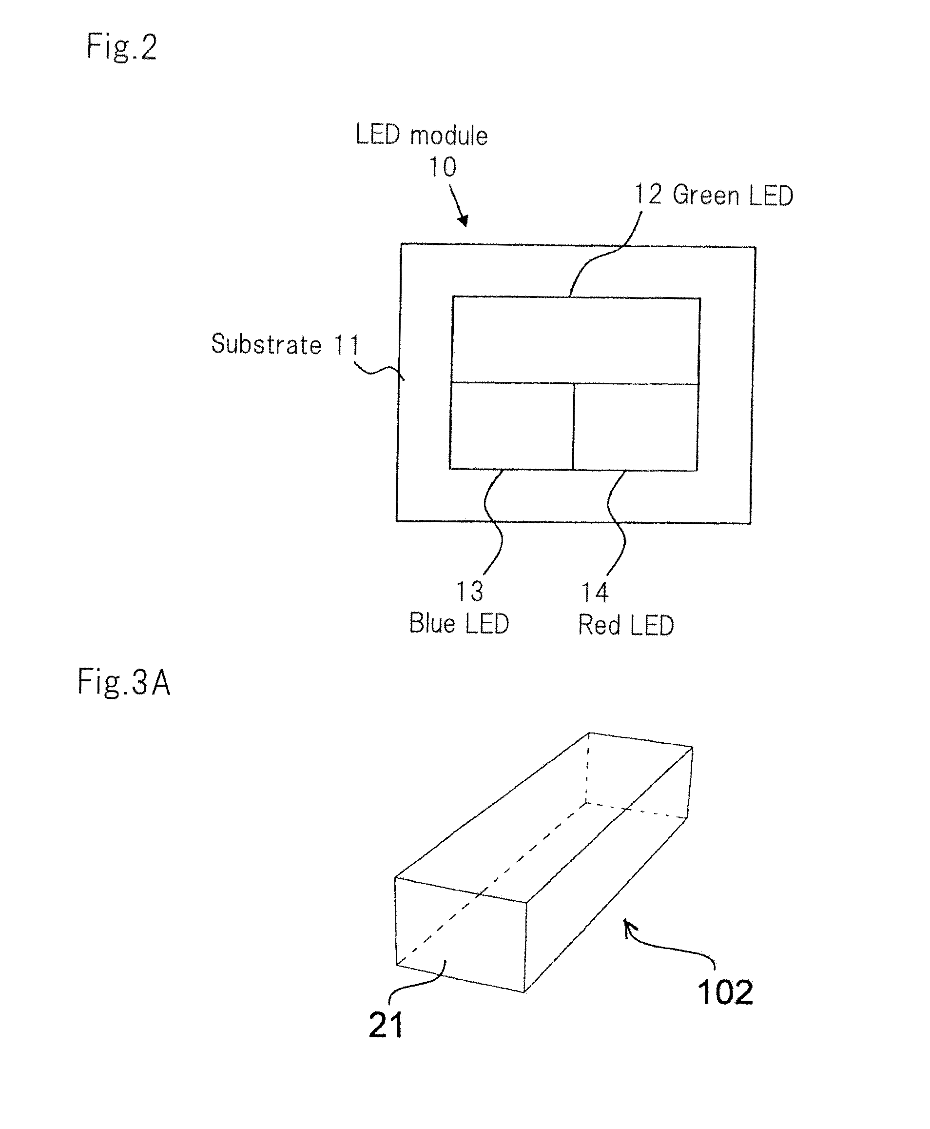
[0075]As shown in FIG. 1, the illumination device according to the present embodiment, which illuminates display element 110 having reflective polarizing plate 109, includes, in addition to reflective polarizing plate 109, light source 101, light guiding rod 102, illumination lenses 103, 104, 106, and 107, reflection element 105, and phase plate 108.

[0076]Reflective polarization plate 109 is, for example, a polarization plate of a wire-grid type, and configured to transmit, among incident lights, first polarized light (e.g., P polarized light) while reflecting second polarized light (e.g., S polarized light) in a polarization state that is different from the polarization state of the first polarized light in a direction (toward reflection element 105) opposite an incident direction.

[0077]Display element 110 includes, for example, a liquid cry...


PUM


Abstract

Illumination device includes a light source (101); an illumination optical system (102, 103, 104, 106, 107) that spatially splits each of the plurality of color light beams emitted from the light source, superimposes the split light beams of each of the plurality of color light beams, and emits the superimposed light beams to a display element (110); a reflective polarization plate (109) that is arranged between the illumination optical system (102, 103, 104, 106, 107) and the display element (110) and that transmits first polarized light and reflects second polarized light whose polarization state is different from that of the first polarized light toward the illumination optical system (102, 103, 104, 106, 107); a reflection element (105) that is arranged at a position where each of the plurality of color light beams is spatially split by the illumination optical system and that transmits the split light beams of each of the color light beams and reflects, of the split light beams of each of the color light beams that have been transmitted through the reflective polarization plate (109), each color light beam reflected by the reflective polarization plate toward the reflective polarization plate (109); and a phase plate (108) arranged between the reflection element (105) and the reflective polarization plate (109).

Description

TECHNICAL FIELD[0001]The present invention relates to an illumination device for a projection type display device represented by a liquid crystal projector, in particular, to an illumination device that illuminates a display element including a reflective polarization conversion element.BACKGROUND ART[0002]Patent Literatures 1 and 2 discuss a projector that uses a LED (Light Emitting Diode) as a light source for illuminating a DMD (Digital Micromirror Device) serving as a display element. The projector of this type is expected to reduce costs more than a projector that uses a discharge lamp, and achieve performance including miniaturization, lower power consumption, and a wider color reproduction range.[0003]There are also a projector that uses a single LCoS (Liquid Crystal on Silicon) element (Nonpatent Literature 1), and a projector that users three liquid crystal panels as display elements (Nonpatent Literatures 2 and 3).[0004]In the liquid crystal projector, usually, a liquid cr...

Claims


Application Information

Patent Timeline
IPC IPC(8): G03B21/14F21V13/12F21V13/08
CPCG03B33/06G03B21/2013G03B21/2033G03B21/2073F21V9/14G02B6/24H04N9/3167G02B27/28G02B27/0994G02B6/10F21S10/005G02B1/045G03B21/14
Inventor KATOU, ATSUSHI
Owner SHARP NEC DISPLAY SOLUTIONS LTD
Why Eureka
Try Eureka