Motionless focus evaluation test station for electro-optic (EO) sensors

Active Publication Date: 2012-10-04
RAYTHEON CO
View PDF2 Cites 5 Cited by
  • Summary
  • Abstract
  • Description
  • Claims
  • Application Information

AI Technical Summary

Benefits of technology

[0009]The following is a summary of the invention in order to provide a basic understanding of some aspects of the invention. This summary is not intended to identify key or critical elements of the invention or to

Problems solved by technology

The EO sensor has no dynamic focusing capability to adjust the position of the detector.

Method used


Image

  • Motionless focus evaluation test station for electro-optic (EO) sensors
  • Motionless focus evaluation test station for electro-optic (EO) sensors
  • Motionless focus evaluation test station for electro-optic (EO) sensors

Examples


Embodiment Construction

[0024]The present invention provides a motionless focus evaluation test station for measuring detector position error of an EO sensor that does not possess a dynamic focusing capability. Advantages of the motionless test station may include a smaller foot print and lower system cost by eliminating the linear translation stage, higher throughput and higher fidelity of detector position error measurement.

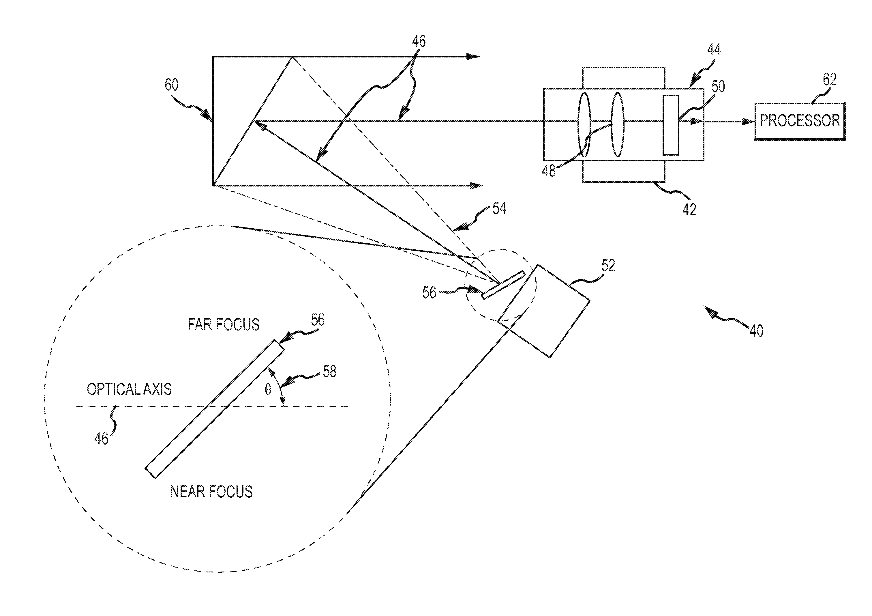
[0025]In an embodiment shown in FIG. 4, a motionless focus evaluation test station 40 comprises a fixture 42 for mounting an EO sensor 44 so that its optical axis is coincident with the test station's optical axis 46. EO sensor 44 comprises an optical assembly 48 that focuses collimated EM radiation onto a detector 50 nominally positioned at a desired detector position (ddesired) such as the back focal plane of the optical assembly.

[0026]A positionally-fixed source 52 emits EM radiation 54 that diverges along optical axis 46. A positionally-fixed target 56 is canted at a non-perpendic...


PUM


Abstract

A motionless focus evaluation test station is provided for measuring detector position error of EO sensors that do not possess dynamic focus capability. A positionally-fixed source emits EM radiation that diverges along an optical axis of the test station. Collimating optics collimate the EM radiation and direct it along the optical axis to the EO sensor. A positionally-fixed target is placed in the path of the diverging EM radiation nominally at the focal plane of the collimating optics. The target comprises a limiting aperture that exhibits an induced shift in optical focus at different positions along the aperture such that different positions on the target are imaged to different focal planes at the detector. The detector captures an image of the target that is blurred to either side of the spatial position that is optically conjugate to the actual detector position. A processor processes the image to measure the blur as function of spatial position to measure the actual detector position and output detector position error from a desired detector position.

Description

BACKGROUND OF THE INVENTION[0001]1. Field of the Invention[0002]This invention relates to focus evaluation test stations for characterizing position error in an EO sensor that does not possess dynamic focusing capability, and more particularly to a motionless test station that does not translate the source and target to vary the apparent axial EO Sensor image position.[0003]2. Description of the Related Art[0004]A particular class of Electro-Optical (EO) sensors comprises an optical assembly that focuses collimated electromagnetic (EM) radiation onto a detector. The detector is nominally positioned at a known desired position. Typically, the detector is positioned at the focal plane of the optical assembly for optimum focus if the system is set for infinity focus. However, it may be desirable to position the detector elsewhere. This class of EO sensor has no dynamic focusing capability to adjust the position of the detector. The detector is responsive to wavelengths of EM radiation ...

Claims


Application Information

Patent Timeline
IPC IPC(8): H04N17/00
CPCH04N5/2253H04N17/002H04N5/33H04N23/54
Inventor EASTON, MICHAEL P.STREUBER, CASEY T.KING, PAGE ELIZABETH
Owner RAYTHEON CO
Why Eureka
Try Eureka