Multiple Compressor System and Method For Locomotives

a compressor system and locomotive technology, applied in the direction of locomotives, machines/engines, electric control, etc., can solve the problems of delay in locomotive departure, inability to power, and traditional air compressor systems of the prior ar

Inactive Publication Date: 2012-11-01
NORFOLK SOUTHERN
View PDF19 Cites 18 Cited by
  • Summary
  • Abstract
  • Description
  • Claims
  • Application Information

AI Technical Summary

Benefits of technology

[0006]In one aspect, the present invention disclosed herein is directed to a compressed air system for a railroad locomotive comprising: a first air compressor; a second air compressor; a layover heater for maintaining the temperature of engine coolant; and a control system, wherein the first air compressor, the second air compressor, the layover heater, and the control package can be powered by at least one of the following power sources: a

Problems solved by technology

Generally, the air compressor is powered by the locomotive engine and is unavailable for use while the locomotive is shut down.
These layover heater systems generally maintain engine coolant above certain temperatures when ambient temperatures are not sufficient to maintain the engine coolant.
The traditional air compressor systems of the

Method used


Image

  • Multiple Compressor System and Method For Locomotives
  • Multiple Compressor System and Method For Locomotives
  • Multiple Compressor System and Method For Locomotives

Examples


Embodiment Construction

[0011]The present application is directed toward the technical field of compressor systems for diesel engines utilizing multiple air compressors, control and power circuits, and a layover heating system.

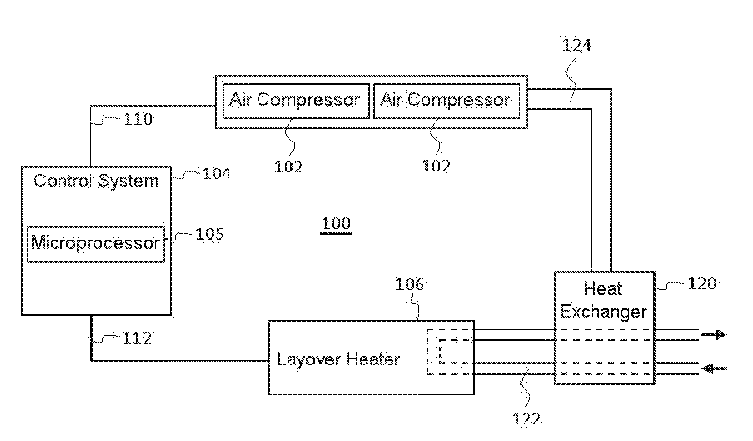
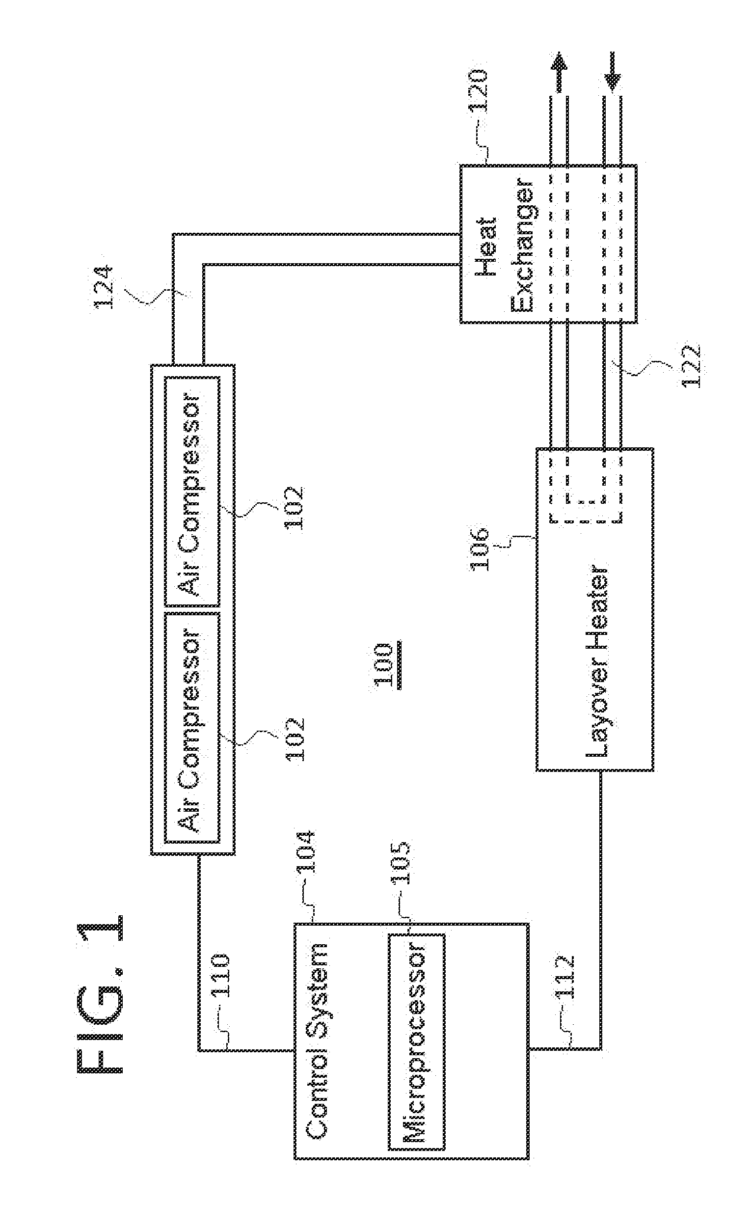
[0012]Referring to FIG. 1, one embodiment of the present invention is depicted. Multiple compressor system 100 may include at least two air compressors 102, a layover heater 106, and a control system 104.

[0013]Each air compressor 102 may be a rotary screw type air compressor, or any other type of air compressor known in the art. Each air compressor 102 may be rated at 60-80% of the minimum industry specified capacity for generating compressed air for locomotive breaking and auxiliary systems. Unlike traditional locomotive air compressor arrangements, air compressors 102 may be powered by shore power in addition to the electrical current generated by the onboard locomotive systems. Shore power may include 440 volt alternating current supplied from the commercial power grid, or any oth...


PUM


Abstract

A system and method for maintaining a supply of compressed air on a locomotive. In one embodiment of the invention a compressed air system for a railroad locomotive comprises: a first air compressor; a second air compressor; a layover heater for maintaining the temperature of engine coolant; and a control system, wherein the first air compressor, the second air compressor, the layover heater, and the control package can be powered by at least one of the following power sources: an onboard electrical power source; or an offboard power source, wherein the layover heater can utilize heat generated by the first air compressor and the second air compressor to maintain the temperature of engine coolant, and wherein the control system operating the compressed air system utilizes a first logic when the power source is the onboard electrical power source and a second logic when the power source is the off board power source.

Description

TECHNICAL FIELD[0001]The present invention is in the field of locomotive diesel engines and compressed air systems. More particularly, the present invention is in the technical field of air compressor systems for diesel locomotive engines utilizing multiple air compressors, control and power circuits, and a layover heating system.BACKGROUND OF THE INVENTION[0002]Air compressor systems for internal combustion engines, such as those powering locomotives, are known in the art for the purpose of generating compressed air to be used in the braking and auxiliary systems of the locomotive. For example, a prior art air compressor system may include a multi-cylinder air compressor with a pair of low pressure cylinders and a high pressure cylinder mounted on and supported by a crankcase. Generally, the air compressor is powered by the locomotive engine and is unavailable for use while the locomotive is shut down.[0003]Layover heater systems for internal combustion engines are also known in th...

Claims


Application Information

Patent Timeline
IPC IPC(8): B61C17/00
CPCB61C17/00F02D23/00F02D29/02F01P2060/18F02D41/042Y02T10/144F02D41/0007Y02T10/12
Inventor GRAAB, DONALD DIETRICHBACKUS, BRUCE EDWARD
Owner NORFOLK SOUTHERN
Why Eureka
Try Eureka