

Light source device and projector
- Summary
- Abstract
- Description
- Claims
- Application Information
AI Technical Summary
Benefits of technology
Problems solved by technology
Method used
Image

Examples
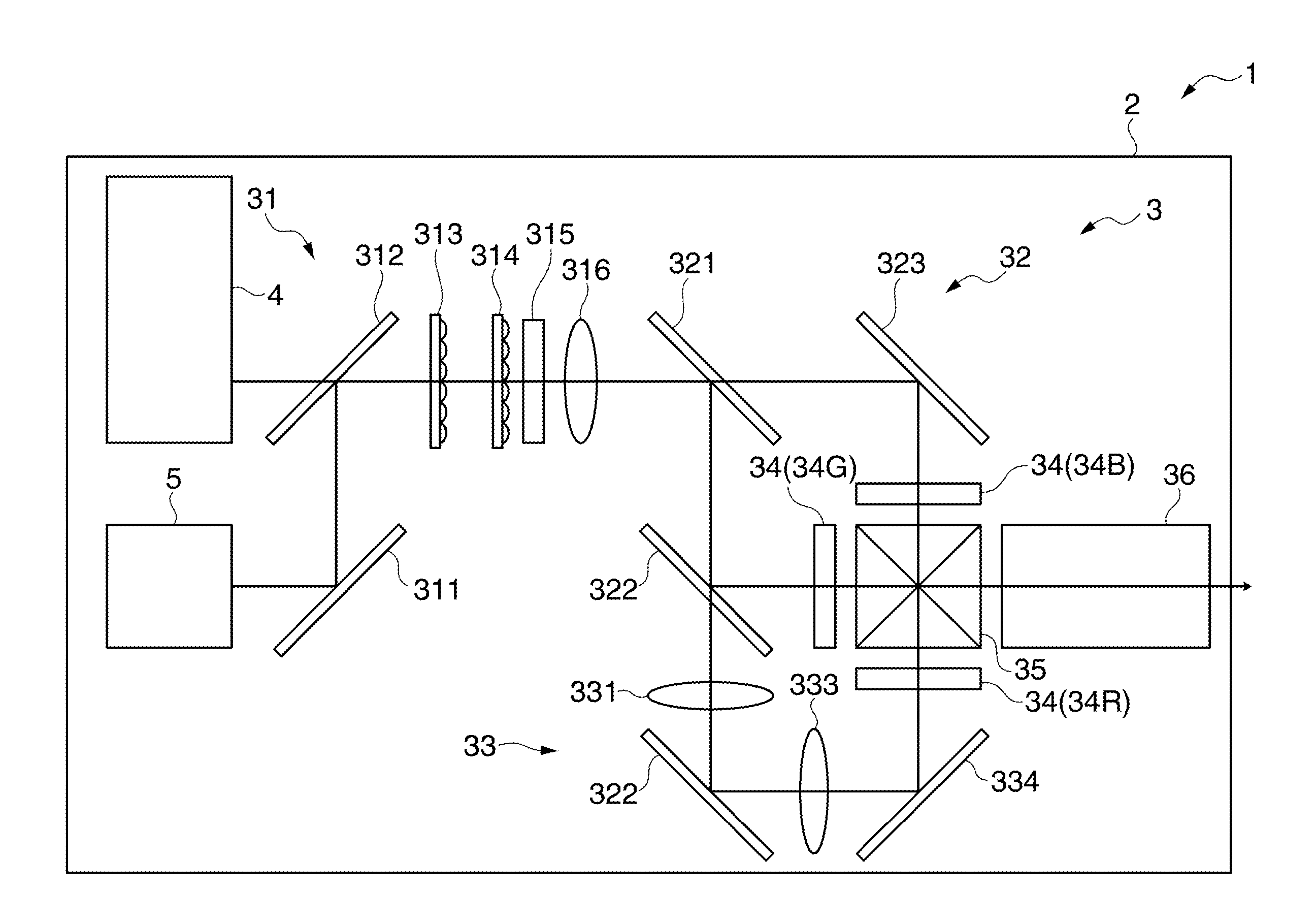
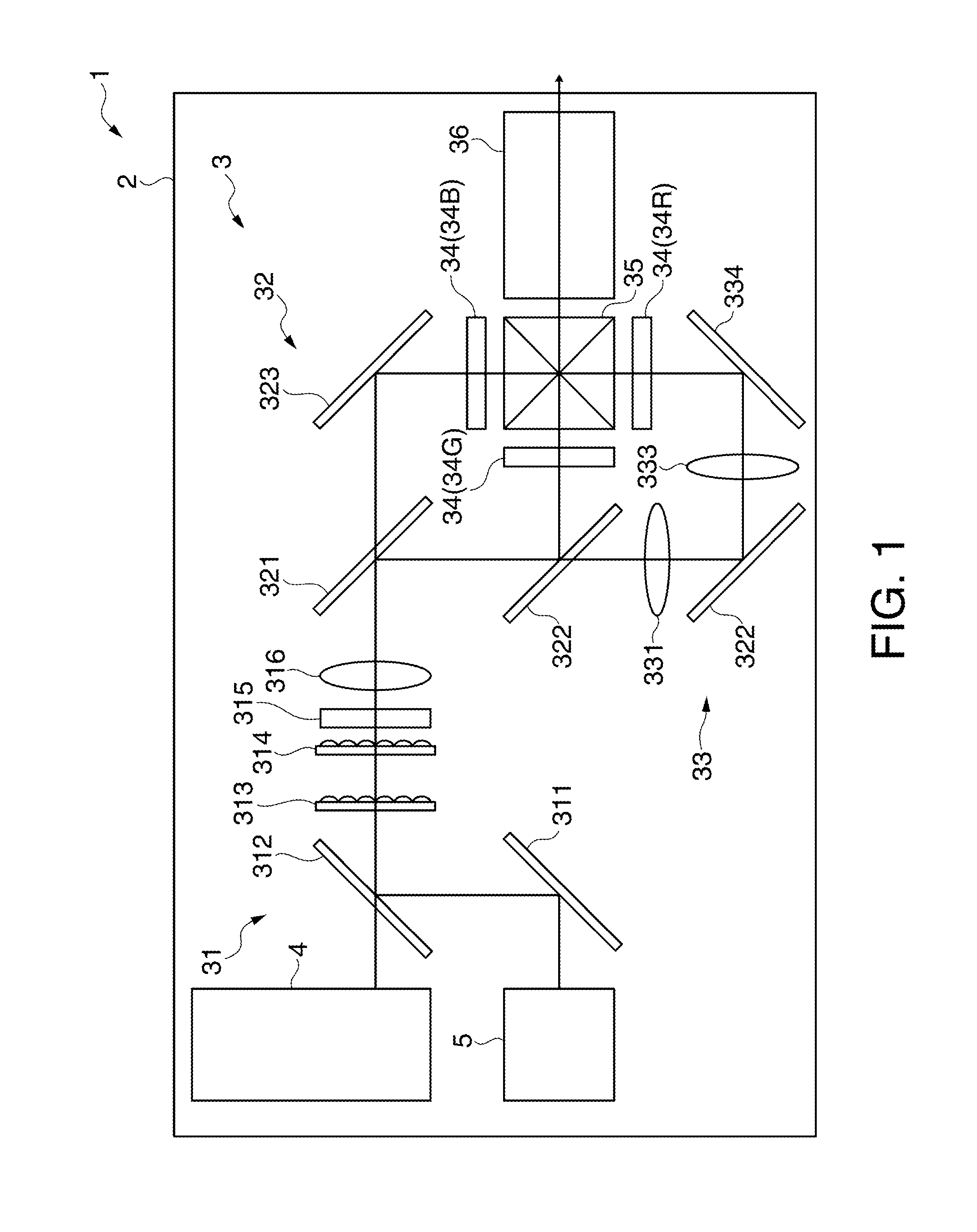
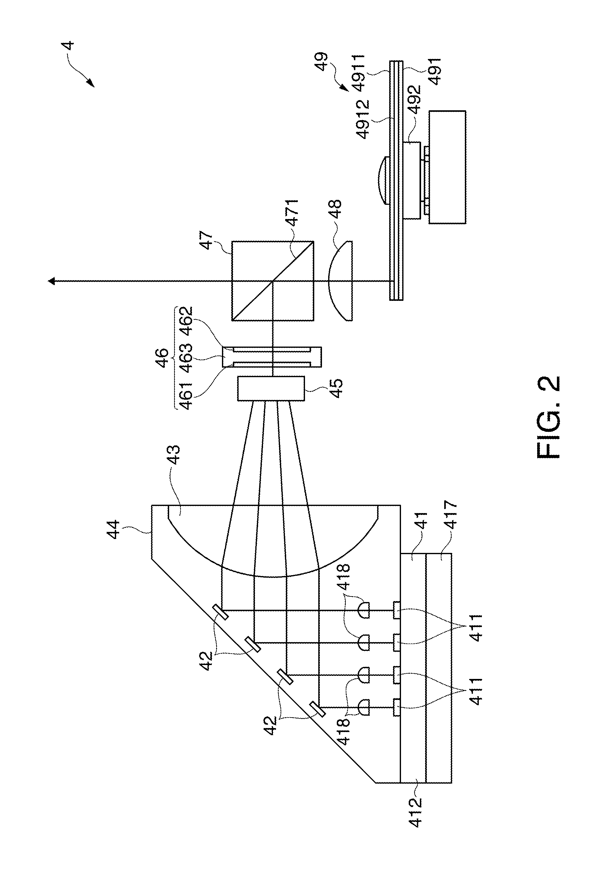
first embodiment
Modification of First Embodiment
[0120]FIG. 7 is a view illustrating a modification of the pressing member 414 according to this embodiment.
[0121]In this embodiment, it is described that the respective projections 4142 of the pressing member 414 are formed in a substantially trapezoidal shape in plan view in which the width dimension becomes smaller as the projections of the pressing member 414 is directed to the center of the opening 4141. However, instead of the pressing member 414, a pressing member 611 of which the respective projections 6112 are formed in a rectangular shape in plan view can be used.
[0122]This pressing member 611, as shown in FIG. 7, has the same configuration and function as the above-described pressing member 414 except that the pressing member 611 has the rectangular-shaped projections 6112 in plan view instead of the projections 4142 of the substantially trapezoidal shape. That is, the pressing member 611 has the opening 6111 that is the same as the opening ...
second embodiment
[0125]Hereinafter, a second embodiment of the invention will be described.
[0126]Although the projector according to this embodiment has the same configuration and function as the above-described projector 1, it differs from the projector 1 on the point that each of the respective solid-state light sources 411 is pressingly fixed to the base member 412 by one pressing member.
[0127]In the following description, the same reference numerals are given to portions that are the same as or substantially the same as the above-described portions and the description thereof will not be repeated.
[0128]FIG. 8 is a plan view illustrating a pressing member 612 of a projector according to this embodiment.
[0129]The projector according to this embodiment has the same configuration and function as the projector 1 except that a plurality of pressing members 612 are provided instead of the pressing member 414 and the fixing member 415.
[0130]As shown in FIG. 8, the pressing members 612 is substantially “...
third embodiment
[0136]Next, the third embodiment of the invention will be described.
[0137]The projector according to this embodiment has the same configuration and function as the above-described projector 1. Here, it is described that according to the projector 1, the extension direction of the projection 4142 from the edge of the opening 4141 in the pressing member 414 crosses the row direction and the column direction, which are the X direction and the Y direction. In the projector according to this embodiment, the extension direction is parallel to the row direction. On this point, the projector according to this embodiment is different from the projector 1. In the following description, the same reference numerals are given to portions that are the same as or substantially the same as the above-described portions and the description thereof will not be repeated.
[0138]FIG. 9 is a plan view illustrating a pressing member 613 of a projector according to this embodiment.
[0139]The projector accordi...
PUM
 Abstract
Description
Claims
Application Information