Hand-held ink stamper with spare ink supply

Inactive Publication Date: 2006-07-06
COSCO IND
View PDF4 Cites 12 Cited by
  • Summary
  • Abstract
  • Description
  • Claims
  • Application Information

AI Technical Summary

Benefits of technology

[0007] The problems mentioned above are solved by the present invention in which a spare ink supply, such as an ink pad, is conveniently located on the stamper itself for easy replacement of a used ink pad. More specifically, a hand-held ink stamper has a base, an actuator slidably disposed on the base, and a die mount movably mounted within the base. The die mount is connected to the actuator and movable to at le

Problems solved by technology

Since a replacement ink pad is stored separately from the stamper, the ink pads can be lost, may r

Method used


Image

  • Hand-held ink stamper with spare ink supply
  • Hand-held ink stamper with spare ink supply
  • Hand-held ink stamper with spare ink supply

Examples


Example

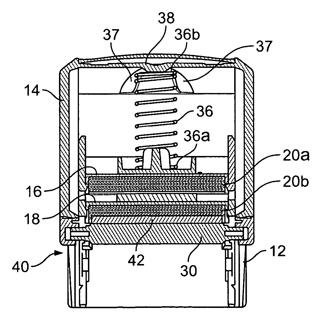
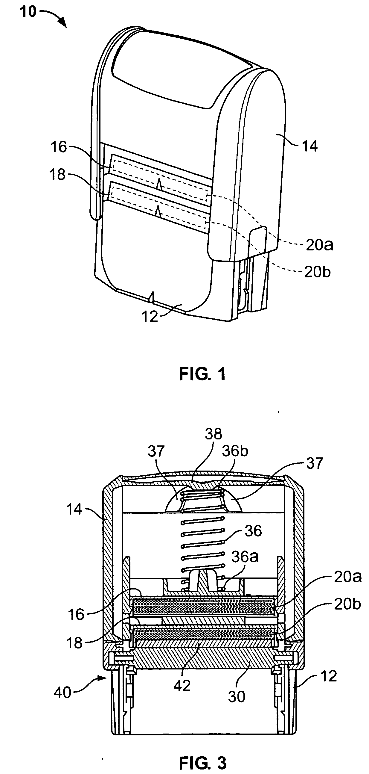
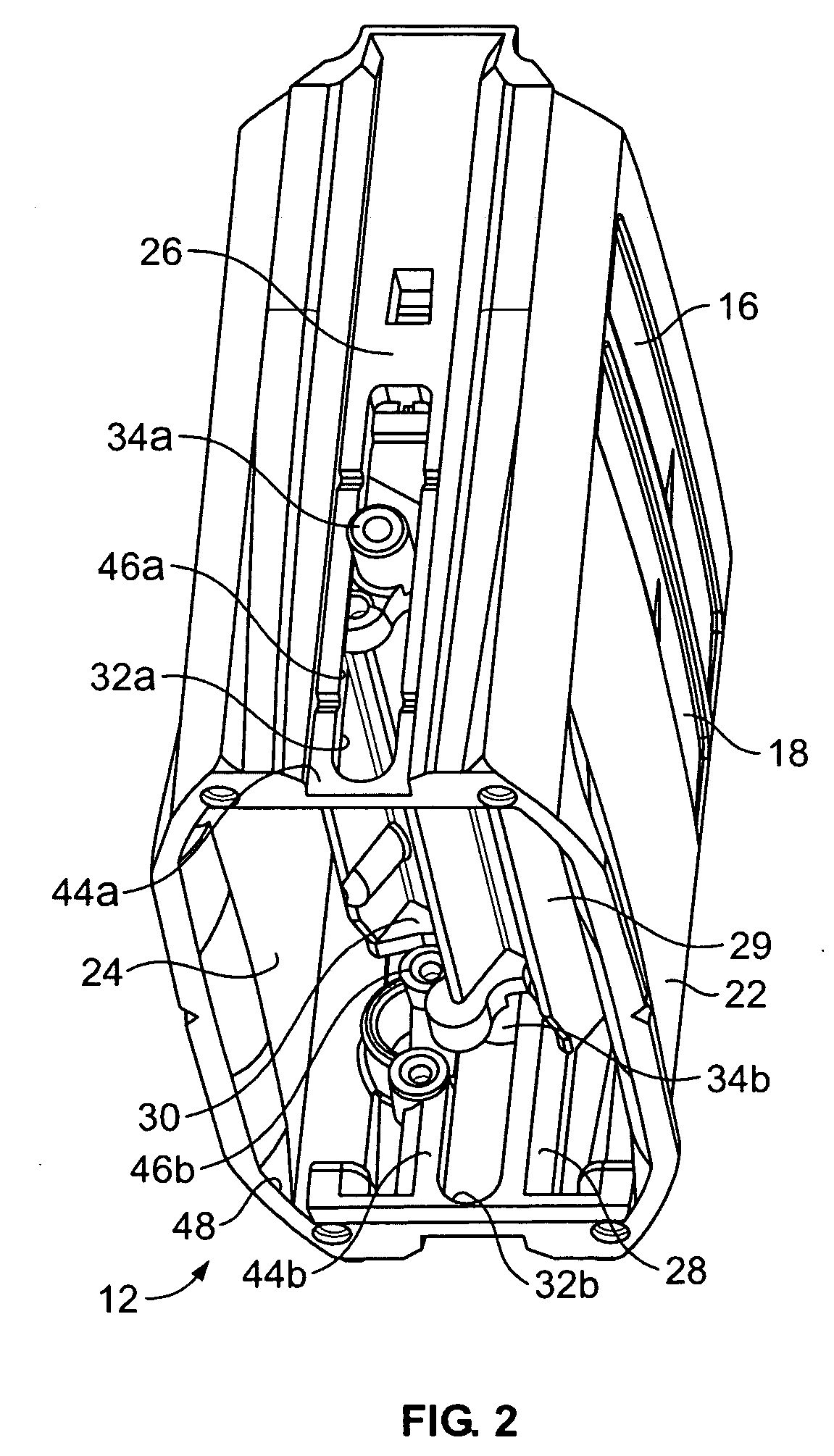
[0024] Referring to FIG. 1, a hand-held, self-inking stamper 10 has a base 12 and an actuator 14 mounted on the base 12. The actuator 14 acts as a handle and slides up and down over the base 12 in order to operate the stamper. The base 12 has at least two removable drawers or trays 16 and 18 for respectively holding an ink supply such as ink containers or ink pads 20a, 20b as described in more detail below. The actuator 14 is shaped to slide over the trays 16 and 18 when operating the stamper.

[0025] As shown in FIG. 2, the base 12 has a front wall 22 opposing a symmetrical, back wall 24, and a left sidewall 26 opposing a symmetrical, right sidewall 28. Since ink stamper 10 is a self-inking stamper, it has a die mount 29 such as a rotating pintel 30 that is rotatably mounted to the base 12 through slots 32a and 32b respectively formed on sidewalls 26, 28. The pintel 30 has posts 34a and 34b extending through the slots and connecting to the actuator 14 on the exterior side of the sid...


PUM


Abstract

A hand-held ink stamper has a base, an actuator slidably disposed on the base, and a die mount movably mounted within the base. The die mount is connected to the actuator and movable to at least a printing position upon movement of the actuator. A die is mounted on the die mount. A first, removable ink supply is mounted within the base at a first position and provides ink to the die. At least one second, spare, removable ink supply is stored within the base at a second position. The second ink supply is removable for replacing the first ink supply by moving the second ink supply to the first position.

Description

TECHNICAL FIELD OF THE INVENTION [0001] The invention relates generally to hand-held ink stampers, and more particularly to ink stampers that hold an extra ink pad on the stamper. BACKGROUND OF THE INVENTION [0002] Conventional hand-held, self-inking ink stampers, like that disclosed in U.S. Pat. No. 5,649,485 issued to Door et al., have a rotating pintel that holds a die plate with a word or design to be printed. By actuating the stamper, the pintel can be swiveled between an inking position, where the pintel faces the interior of the stamper, and a printing position, where the pintel faces the exterior of the stamper. In the inking position, the die plate faces an ink pad positioned in an everted, removable tray that slides in and out of the side of the stamper for replacement. [0003] Since a replacement ink pad is stored separately from the stamper, the ink pads can be lost, may require interruption of work to obtain or may use storage space that could be used for other things. [...

Claims


Application Information

Patent Timeline
IPC IPC(8): B41K1/42
CPCB41K1/40B41K1/52
Inventor MOODY, BRETT
Owner COSCO IND
Why Eureka
Try Eureka