Lock for vehicle doors or lids

Inactive Publication Date: 2008-03-11
HUF HULSBECK & FURST GMBH & CO KG
View PDF10 Cites 11 Cited by
  • Summary
  • Abstract
  • Description
  • Claims
  • Application Information

AI Technical Summary

Benefits of technology

[0010]In the invention, there is only an indirect connection between the cam and the rotary catch, namely, the connection established by the pair of toggle-joint levers and the driver articulated to them. So that the inventive lock can be applied to vehicles of different types, the cam, which has a certain defined control curve, can be easily replaced by a cam with a control curve of a different profile, the rest of the lock remaining unchanged. If necessary, however, it is possible, supplemen

Problems solved by technology

This lock has proven to be reliable, but it is bulky and expensive.
This not only requires the production and assembly of different lock elements, but also demands more complicated inventory control and increases the difficulty of repairing defective locks.
Thus, for example, in the case of the previously mentioned known lock, it is not possible, when a change i

Method used


Image

  • Lock for vehicle doors or lids
  • Lock for vehicle doors or lids
  • Lock for vehicle doors or lids

Examples


Example

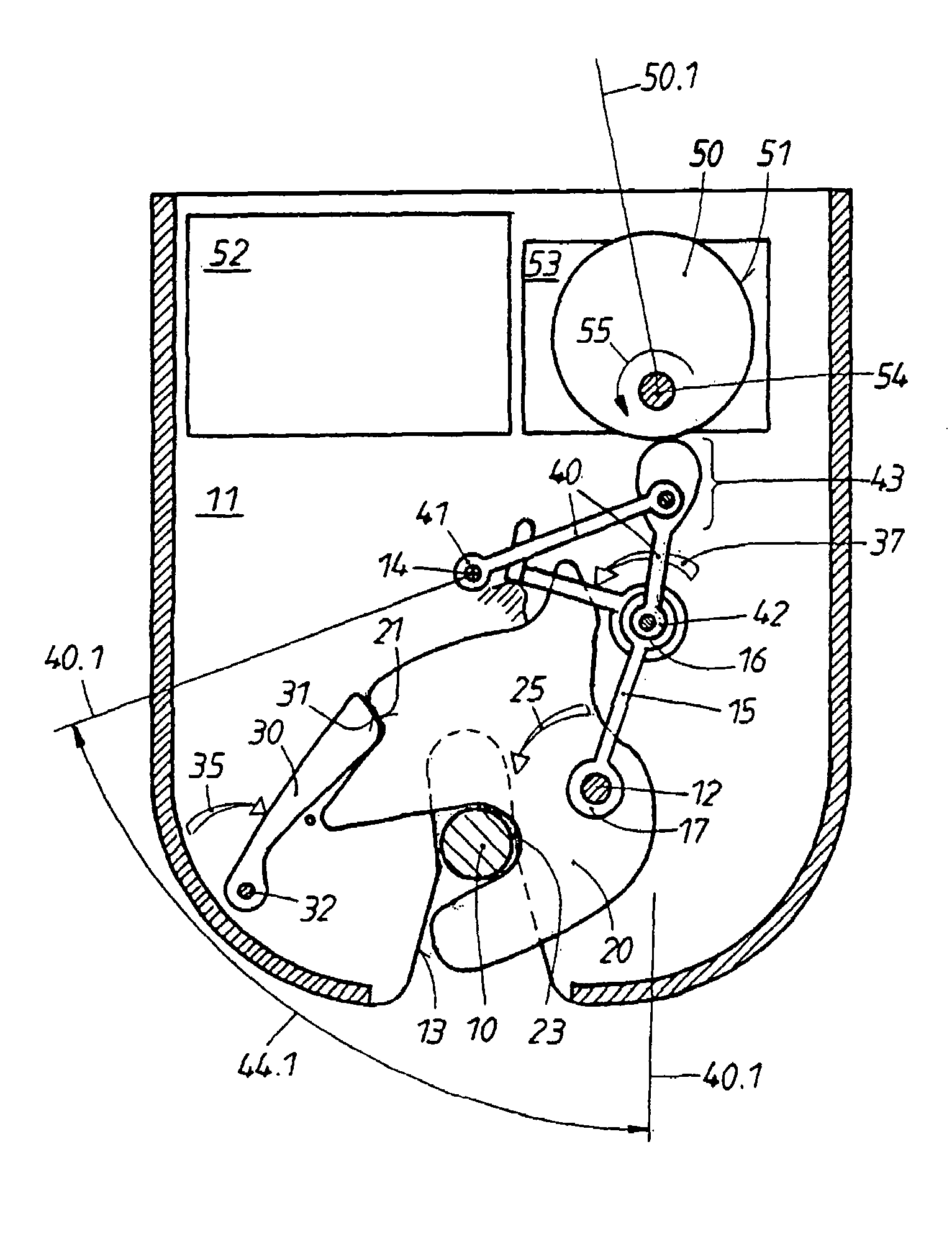
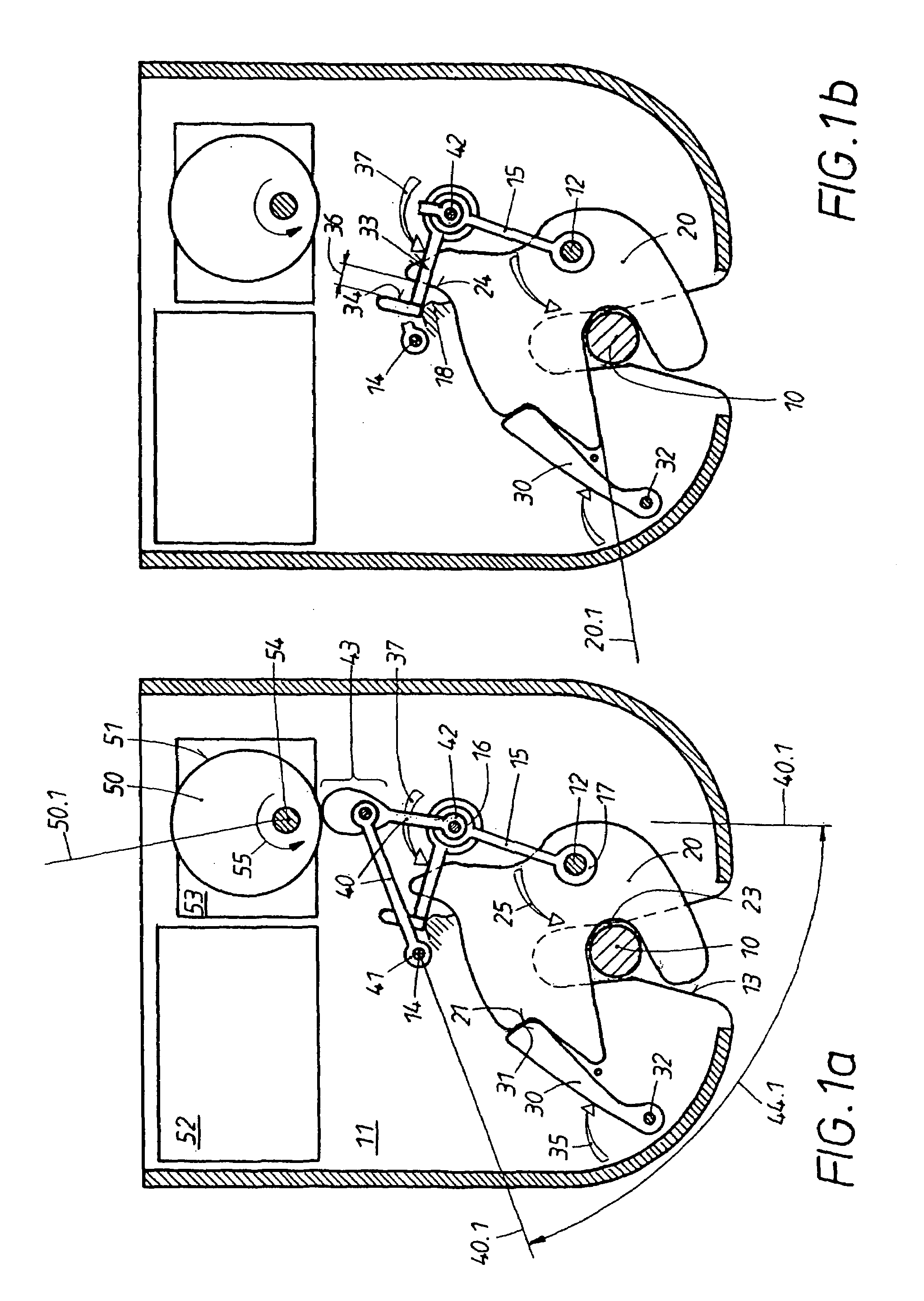
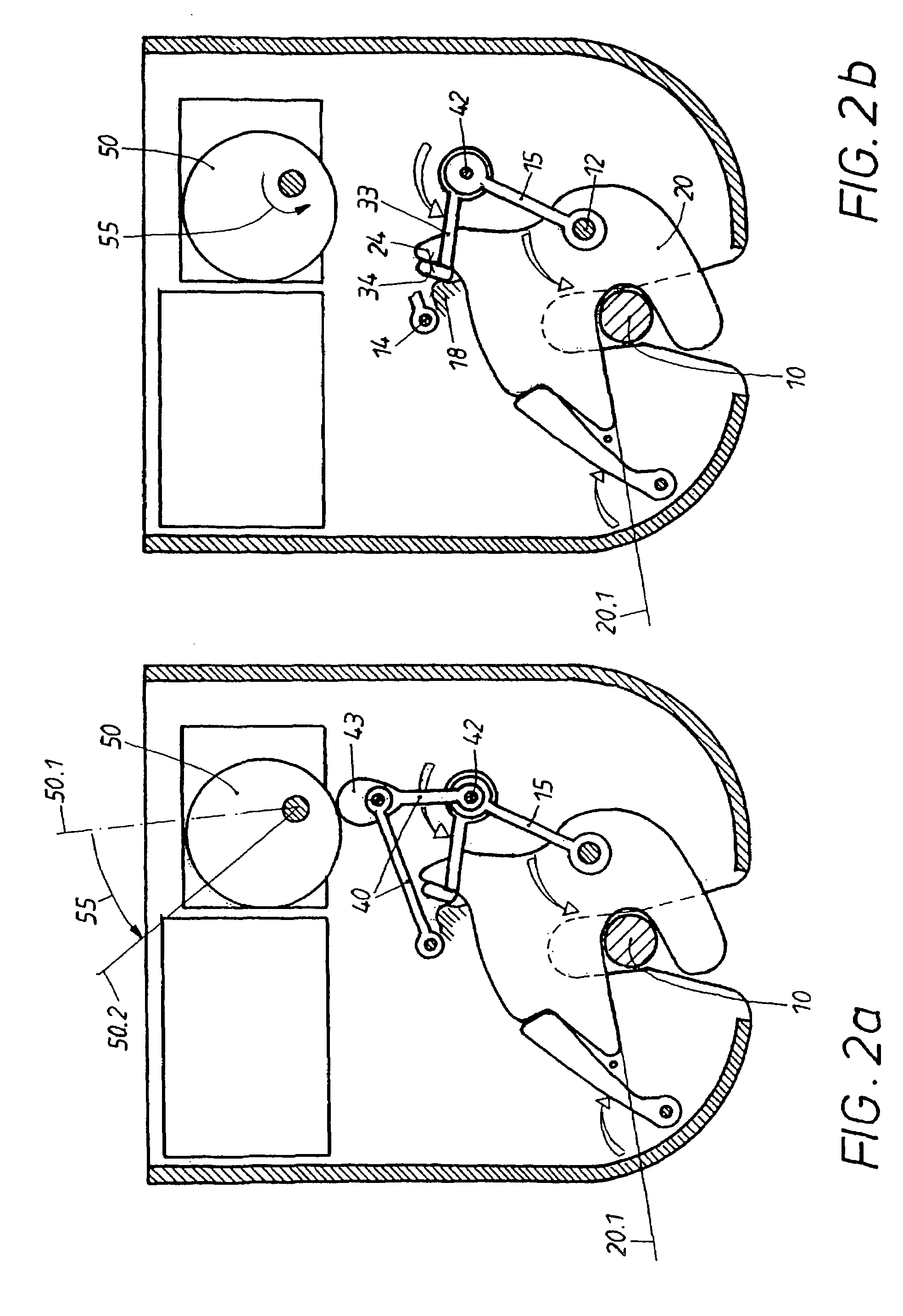
[0018]The lock has a lock housing 11 mounted on the door and a locking part 10 seated on the door post. In the lock housing 11, a rotary catch 20, which has a receptacle 23 for the locking part 10, is seated on a first, stationary bearing pin 12. When the door is open, the rotary catch is in its open position (not shown) in the lock housing 11, where the opening of the receptacle 23 is aligned with the slot 13 in the housing 11. The rotary catch 20 is spring-loaded in the direction toward its open position, as illustrated by the arrow 25 in FIG. 1a, and when in the open position it rests against end stops (not shown).

[0019]The door is first closed manually. As this happens, the locking part 10 travels into the receptacle 23, strikes the inner sidepiece, and thus rotates the catch 20 in the direction opposite its spring loading 25 until it reaches the “pre-latching position”, characterized by the auxiliary line 20.1 in FIG. 1b. In this pre-latching position 20.1, a pawl 30, which is ...


PUM


Abstract

According to the invention, when the door is locked, a locking part (10) is displaced into a rotary latch (20), which is first pivoted from its open position into a preliminary detent position. The rotary latch (20) is spring-loaded (25) in the direction of its open position and is usually supported on a catch (30) by means of an initial detent section (21). The rotary latch (20) is then rotated further by means of a motor-driven closing aid with the aid of a drive mechanism (53) and an eccentric element (50), until it reaches a primary detent position, in which the catch (30) rests on a primary detent section of the rotary latch (20). To obtain a reliable lock that can be universally used, a toggle-joint lever pair (40) and a spring-loaded follower (33) are provided between the eccentric element (50) and the rotary latch (20). One fixed end (41) of said toggle-joint lever pair (40) is rotatably mounted in a locally fixed bearing (14) and the other free end (42) is forcibly guided by guide elements (15) and simultaneously supports the spring-loaded follower (33). The toggle-joint lever pair (40) is supported on a control curve (51) of the eccentric element (50). The closing displacement is attained by the extension and/or bending of the toggle-joint lever pair. The follower then seizes the rotary latch (20) and propels it in a motor driven manner from its preliminary detent position into its primary detent position.

Description

BACKGROUND OF THE INVENTION[0001]1. Field of the Invention[0002]The invention pertains to a lock which is installed in the area of the door or hatch and has a rotary catch. A locking part is located on the door post, and when the door or hatch is closed by hand, the locking part travels into the rotary catch, thus pivoting it initially from a spring-loaded open position into a pre-latching position. The pre-latching position of the rotary catch is secured by a spring-loaded pawl. Then the motor of a door-closing assist mechanism is turned on by control means. This mechanism, operating by way of a gearbox and a cam, moves the rotary catch from the prelatching position to the main latching position. The main latching position of the rotary catch is also secured by the pawl, which engages with a main notch provided on the rotary catch.[0003]2. Description of the Related Art[0004]Locks with motorized closing and opening mechanisms are known (WO 98 / 27301 A2), in which the gearbox has two...

Claims


Application Information

Patent Timeline
IPC IPC(8): E05C3/06E05B65/12E05B65/32
CPCE05B81/20E05B85/243Y10T292/1047Y10T292/1082E05B85/20E05B81/24
Inventor TORKA, ARTURWIETKAMP, STEPHAN
Owner HUF HULSBECK & FURST GMBH & CO KG
Why Eureka
Try Eureka