
Wireless device, sensor unit, wireless unit, and method for setting wireless device

Active Publication Date: 2014-05-01
YOKOGAWA ELECTRIC CORP
View PDF11 Cites 10 Cited by
  • Summary
  • Abstract
  • Description
  • Claims
  • Application Information

AI Technical Summary

Benefits of technology

The present invention is a wireless device that reduces device certification and enables easy replacement of batteries while keeping the device online even during plant operation. The wireless device consists of a sensor unit and a wireless unit, which communicate wirelessly through a network. The sensor unit measures the flow volume of a fluid, while the wireless unit sends and receives various types of information with the sensor unit using local communication. This setup reduces the likelihood of device certification and allows for easy replacement of batteries while the plant is running.

Problems solved by technology

This explosion-prevention certification requires a more complex procedure than the wireless standard certification mentioned above, and a long time is required to obtain it.
Since the wireless standard certification and the explosion-prevention certification must be obtained separately in each country and region, for makers and vendors of wireless field devices and the like who attempt to expand their business on a world scale, there is a problem that enormous time, cost, and manpower are needed.
Thus there is a problem that the input / output unit is unable to measure and manipulate the state quantity (i.e. it goes offline) while the battery is being replaced.
In the case of a wireless field device installed at a location where explosions must be prevented (an explosion-prevention area), the battery cannot be replaced while the plant is operating unless both the wireless field device and the battery meet explosion-prevention standards.
With the former method, the opportunity to replace the battery is limited to a time when the plant has stopped operating; in addition, a great many batteries must be replaced mechanically in a short time.
Consequently, there is a problem that even batteries with sufficient residual capacity are inevitably replaced.
With the latter method, since the wireless field device must be removed and then reinstalled, there is a problem that considerable time and cost is required.

Method used


Image

  • Wireless device, sensor unit, wireless unit, and method for setting wireless device
  • Wireless device, sensor unit, wireless unit, and method for setting wireless device
  • Wireless device, sensor unit, wireless unit, and method for setting wireless device

Examples


Embodiment Construction

[0049]The present invention will be now described herein with reference to illustrative preferred embodiments. Those skilled in the art will recognize that many alternative preferred embodiments can be accomplished using the teaching of the present invention and that the present invention is not limited to the preferred embodiments illustrated herein for explanatory purposes.

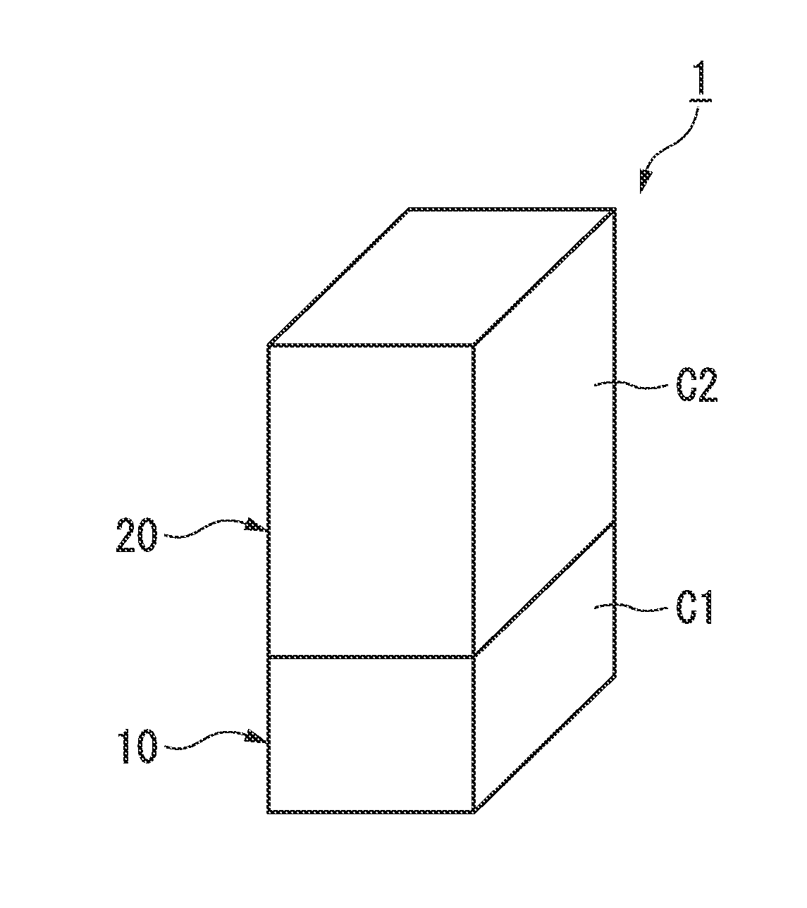
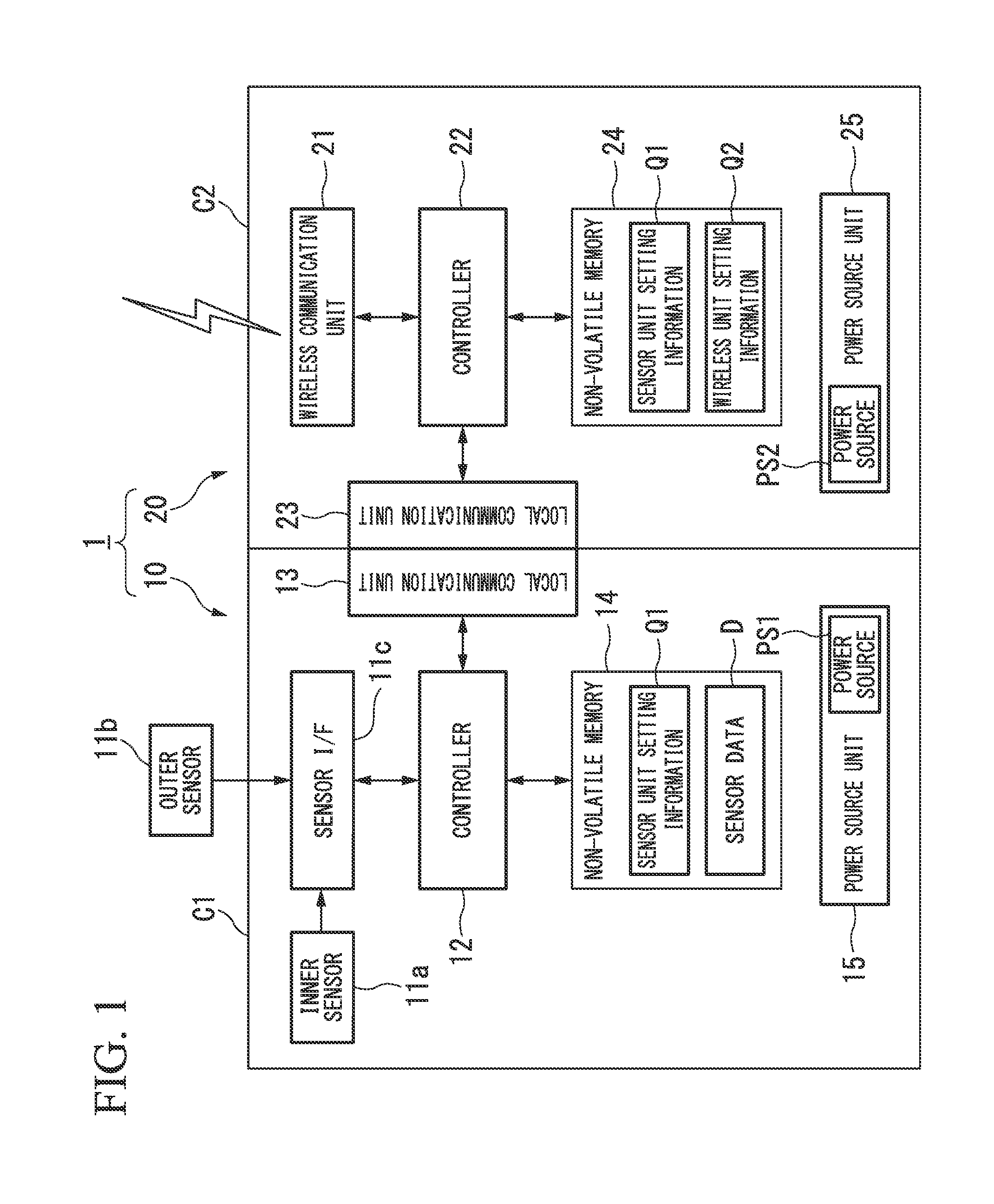
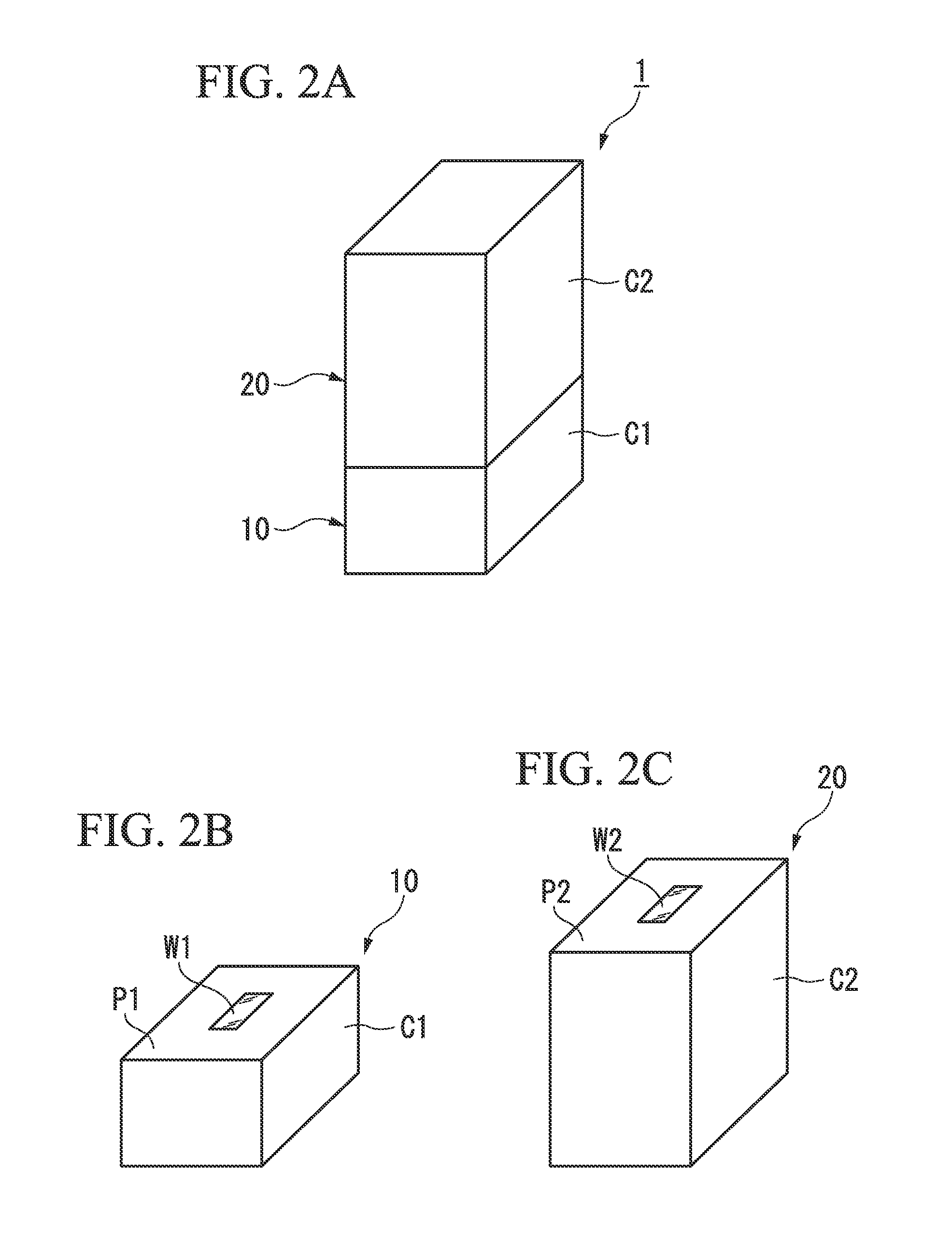
[0050]A wireless device, a sensor unit, a wireless unit, and a method for setting a wireless device in accordance with a first preferred embodiment of the present invention will be described in detail. FIG. 1 is a block diagram illustrating the configuration of main units of a wireless device in accordance with the first preferred embodiment of the invention. As illustrated in FIG. 1, a wireless device 1 of the first preferred embodiment includes a sensor unit 10 and a wireless unit 20. The wireless device 1 measures a state quantity in an industrial process and transmits a measurement result to a wireless netwo...


PUM


Abstract

A wireless device may include a sensor unit and a wireless unit. The sensor unit may include: an input / output unit that measures or manipulating a state quantity in a process; a first local communication unit that performs local communication to transmit / receive measurement results or manipulation commands for the input / output unit; and a first supply unit that supplies power to the input / output unit and the first local communication unit. The wireless unit may include: a wireless communication unit that transmits / receives the measurement results or the manipulation commands for the input / output unit; a second local communication unit that performs local communication with the first local communication unit to transmit / receive the measurement results or the manipulation commands for the input / output unit; and a second supply unit that supplies power to the wireless communication unit and the second local communication unit.

Description

BACKGROUND OF THE INVENTION[0001]1. Field of the Invention[0002]The present invention relates to a wireless device, a sensor unit, a wireless unit, and a method for setting the wireless device.[0003]Priority is claimed on Japanese Patent Application No. 2012-238749, filed Oct. 30, 2012, and Japanese Patent Application No. 2013-168897, filed Aug. 15, 2013, the contents of which are incorporated herein by reference.[0004]2. Description of the Related Art[0005]All patents, patent applications, patent publications, scientific articles, and the like, which will hereinafter be cited or identified in the present application, will hereby be incorporated by reference in their entirety in order to describe more fully the state of the art to which the present invention pertains.[0006]Conventionally, to achieve a high degree of automation at a plant, a factory, and the like, a distributed control system (DCS), in which on-site devices known as field devices (measuring devices and manipulating d...

Claims


Application Information

Patent Timeline
IPC IPC(8): H04W52/02
CPCH04W52/0209G01D11/245G01D21/00
Inventor YAMAJI, MASATO
Owner YOKOGAWA ELECTRIC CORP
Learn More