Petroleum well intervention winch system

Active Publication Date: 2014-06-26
CAPWELL
View PDF13 Cites 12 Cited by
  • Summary
  • Abstract
  • Description
  • Claims
  • Application Information

AI Technical Summary

Benefits of technology

[0025]FIG. 10 is a perspective view and partial section view of a pressure can for being integrated with the wall of the high pressure housing, with an inner rotor for being connected to the external motor such as the capstan or the drum motors, and an outer rotor arranged at the internal, high pressure side within the high pressure housing. The magnet set at the inner rotor provides torque through the pressure can cyli

Problems solved by technology

The sealing devices create much friction towards the moving wireline both on its way into and out of the well.
Further, the sealing devices are subject to wear and constitute a potential point of leakage from the well to the environme

Method used


Image

  • Petroleum well intervention winch system
  • Petroleum well intervention winch system
  • Petroleum well intervention winch system

Examples


Example

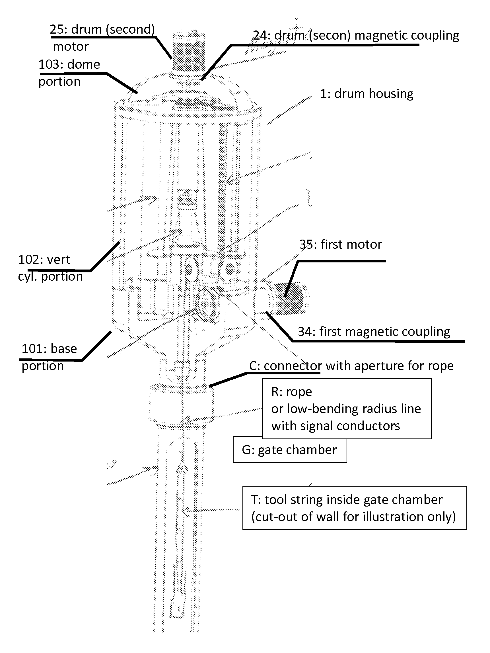
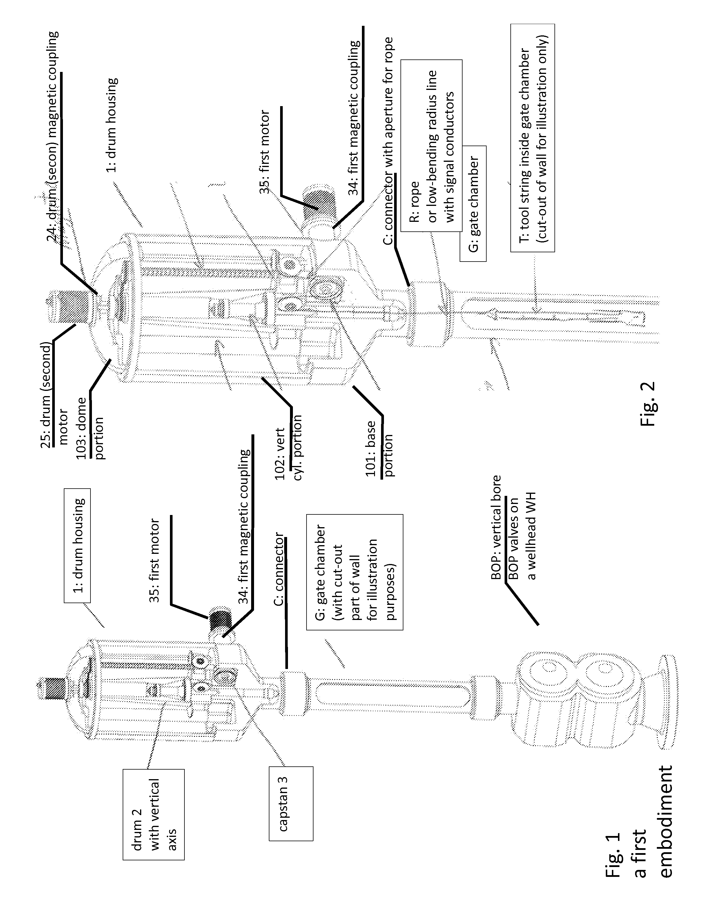
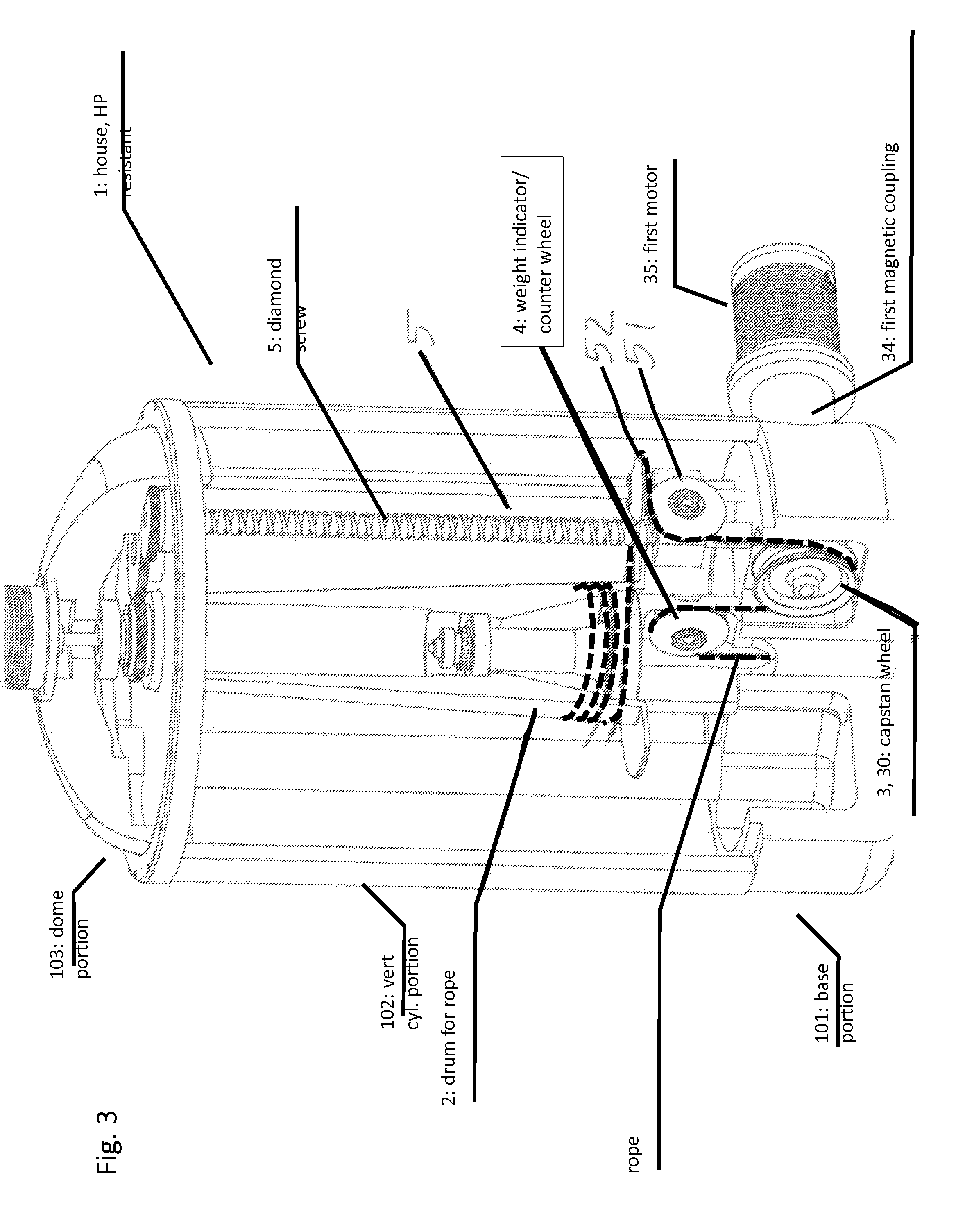
[0031]The invention is petroleum well intervention winch system comprising a high pressure confining housing (1) for a drum (2) for a rope (R) to a tool string (T). The pressure confining housing (1) has a connector (C) with an aperture (A) for said rope (R) to a top of a tool string gate chamber (G) on vertical bore BOP valves on a wellhead (WH) on the petroleum well. The rope from said tool string (T) runs through the aperture (A) via a capstan (3) to the drum (2).Please see FIGS. 2, 4 and 5 for a first embodiment of the invention having one single-wheel capstan (3),and FIGS. 6, 7 and 8 for a second embodiment having a dual-wheel capstan (3, 31, 32).

[0032]The entire system provides that the drum and all moving parts are encapsulated in a pressure compartment (1) which is equalized with the well pressure before operation starts and during the operation. This eliminates the need for stuffing boxes and seals around the line and hence significantly reduces potential risks of leakage.

[...


PUM


Abstract

A petroleum well intervention winch system includes a high pressure confining housing for a drum for a rope to a tool string. The pressure confining housing has a connector with an aperture for the rope to a top of a tool string gate chamber on vertical bore BOP valves on a wellhead on the petroleum well. The rope runs through the aperture via a capstan to the drum. The capstan is driven by a first motor through a first high pressure proof magnetic coupling across a wall of the housing. The drum is driven by a second motor through a second high pressure proof magnetic coupling across the wall of the housing. The capstan is subject to a load tension from the rope and is provided with a hold tension on the rope from the drum. The second motor exerts a constant hold tension on the rope via the drum.

Description

INTRODUCTION[0001]The present invention relates to a petroleum well intervention winch system. The system uses a bending flexible rope in order to provide reduced size of the drum and all sheaves and wheels over which the rope passes. The system includes all moving components confined in a high-pressure housing, and has a capstan drive for taking the load of the rope running with the toolstring in the well. The invention allows for a slender and robust vertically extending unit for being mounted on a toolstring gate chamber on a wellhead, the winch system for operating under well pressure when the access well is open.BACKGROUND ART[0002]There are traditionally two types of line used for wireline operations: so-called slick-line, and twisted conductor cable. In both types the line is fed into the well through a stuffing box with seals. The sealing devices create much friction towards the moving wireline both on its way into and out of the well. Further, the sealing devices are subjec...

Claims


Application Information

Patent Timeline
IPC IPC(8): E21B23/14
CPCE21B23/14E21B33/037E21B33/076E21B41/0007E21B41/06E21B19/008E21B47/135
Inventor TALGO, MORTENHELVIK, JOHN
Owner CAPWELL
Why Eureka
Try Eureka