Electrical connector assembly

a technology of electrical connectors and assembly parts, which is applied in the direction of coupling contact members, fixed connections, coupling device connections, etc., can solve the problems of not easy to inspect the fastening of pcb and ffc and the electrical connection, the assembly is found in the electrical connector assembly, and the rated (i.e.) can not be easily inspected, so as to achieve easy assembly and inspection, increase the maximum current, and easy to apply adhesive coating

Active Publication Date: 2013-05-02
BING XU PRECISION
View PDF52 Cites 11 Cited by
  • Summary
  • Abstract
  • Description
  • Claims
  • Application Information

AI Technical Summary

Benefits of technology

The invention provides several technical benefits. Firstly, it makes it easy to assemble and inspect electrical contacts when connecting the FFC and PCB together in the assembly. Secondly, it makes it easy to apply adhesive and inspect the adhesion when coating the FFC with adhesive on one end. Finally, it increases the number of second contacts on the PCB, which results in a greater maximum current flow through the second soldering holes.

Problems solved by technology

However, a couple of drawbacks have been found in the electrical connector assembly.
First, it is not easy to inspect the fastening of the PCB and the FFC and the electrical connection thereof.
Second, a rated (i.e., maximum) current flowing through the terminals are limited.

Method used


Image

  • Electrical connector assembly
  • Electrical connector assembly
  • Electrical connector assembly

Examples


Embodiment Construction

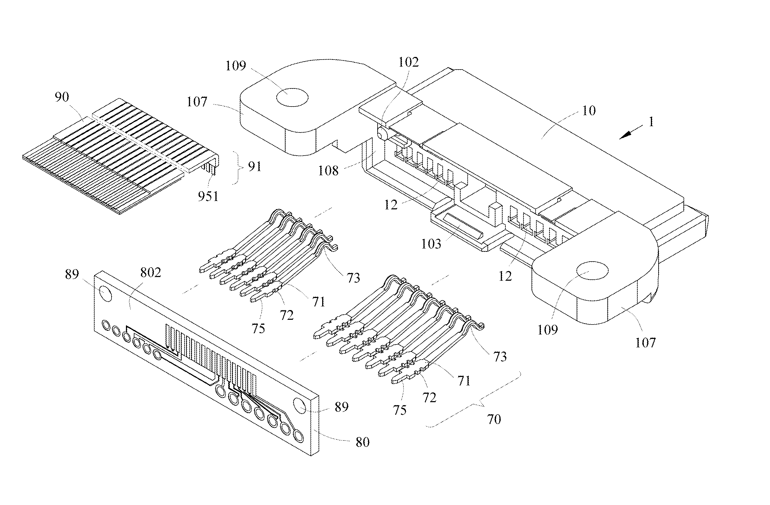
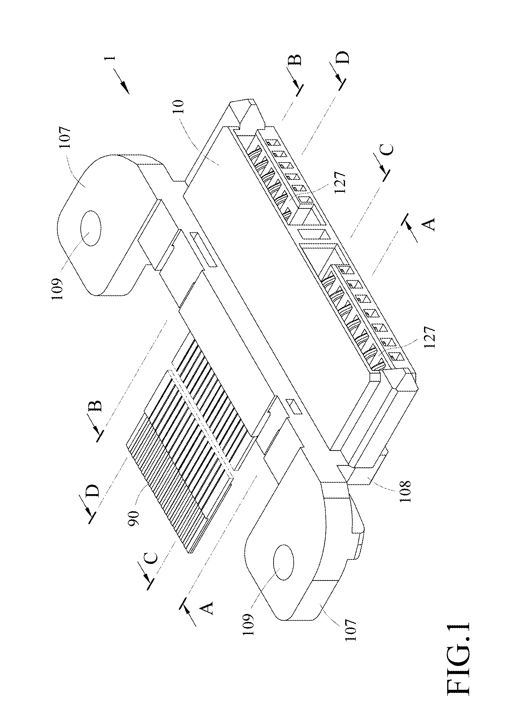
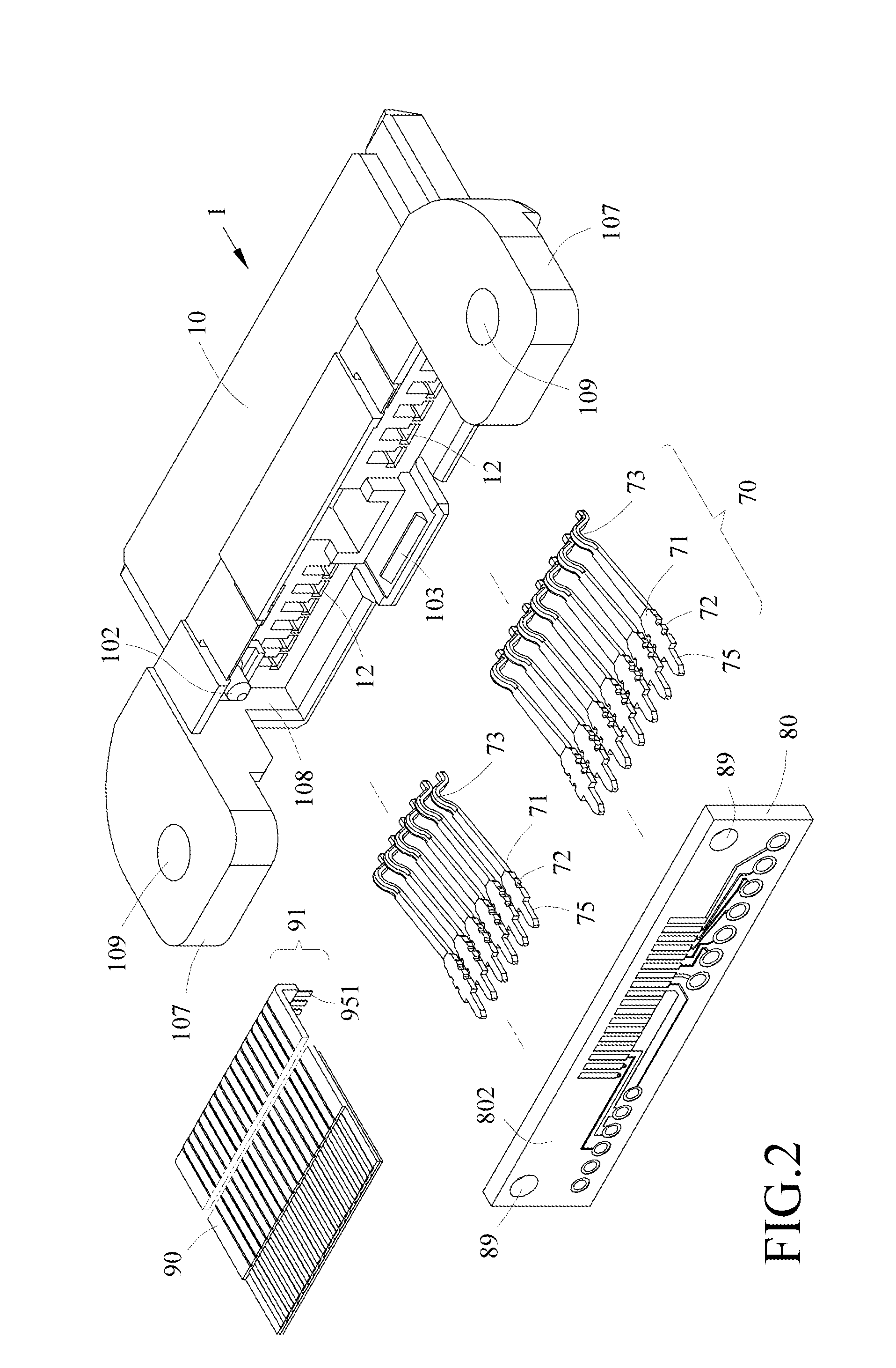
[0027]Referring to FIGS. 1 to 9, an electrical connector assembly (e.g., SATA connector) 1 in accordance with a first preferred embodiment of the invention comprises an insulating housing 10, a plurality of terminals 70, a printed circuit board (PCB) 80, and a (flex (or flexible) flat cable) FFC 90. Each component will be discussed in detail below.

[0028]The insulating housing 10 comprises two extensions 107 on both sides respectively, each extension 107 having a vertical positioning hole 109. The PCB 80 comprises a plurality of first soldering holes 81, a plurality of second soldering holes 82, a plurality of third soldering holes 83, and a plurality of fourth soldering holes 84. The rectangular PCB 80 is a vertically secured to a rear end 108 of the insulating housing 10. A front surface 801 of the PCB 80 faces interior of the insulating housing 10 and a rear surface 802 thereof is distal the interior of the insulating housing 10. A plurality of first contacts 85, a plurality of se...


PUM


Abstract

An electrical connector assembly is provided with an insulating housing, a PCB, and an FFC. The insulating housing includes a plurality of terminals. The FFC and the terminals are electrically connected together by the PCB. The PCB is vertically secured to a rear end of the insulating housing. A plurality of contacts of the PCB are provided on a rear surface of the PCB.

Description

BACKGROUND OF THE INVENTION[0001]1. Field of the Invention[0002]The invention relates to electrical connectors assembly and more particularly to a SATA (Serial Advanced Technology Attachment) connector assembly having a flex flat cable and a printed circuit board which is vertically secured to an insulating housing of the connector assembly and a plurality of contacts of the PCB are provided on a rear surface of the PCB.[0003]2. Description of Related Art[0004]The disclosure of Taiwan Utility Model No. M413,241 entitled “electrical connector assembly”, filed Mar. 28, 2011, is incorporated herein by reference in its entirety. The electrical connector assembly comprises an insulating housing, a printed circuit board (PCB), and a flexible (or flex) flat cable (FFC). The insulating housing includes a plurality of terminals. The FFC and the terminals are electrically connected together by the PCB. The PCB is secured to the insulating housing.[0005]However, a couple of drawbacks have been...

Claims


Application Information

Patent Timeline
Patent Type & Authority Applications(United States)
IPC IPC(8): H01R13/11
CPCH01R12/62H01R24/62H01R2107/00H05K1/117H05K2201/10356H05K2201/0715H05K2201/0949H05K2201/10303H05K3/34
Inventor CHEN, CHIH-JUNG
Owner BING XU PRECISION
Why Eureka
Try Eureka