Cortical drilling

a technology of cortical drilling and implants, which is applied in the field of minimally invasive sinus lift implants and implantation methods, can solve the problems of shoulder slowness but does not stop the advancement of the drill bi

Inactive Publication Date: 2013-06-13
MAXILLENT
View PDF8 Cites 14 Cited by
  • Summary
  • Abstract
  • Description
  • Claims
  • Application Information

AI Technical Summary

Benefits of technology

[0070]coupling the guide stent to the occlusal surface of the occlusal cortex, thereby coupling the support element to the occlusal surface.

Problems solved by technology

Alternatively, the shoulder slows but does not stop the advancement of the drill.

Method used


Image

  • Cortical drilling
  • Cortical drilling
  • Cortical drilling

Examples


Embodiment Construction

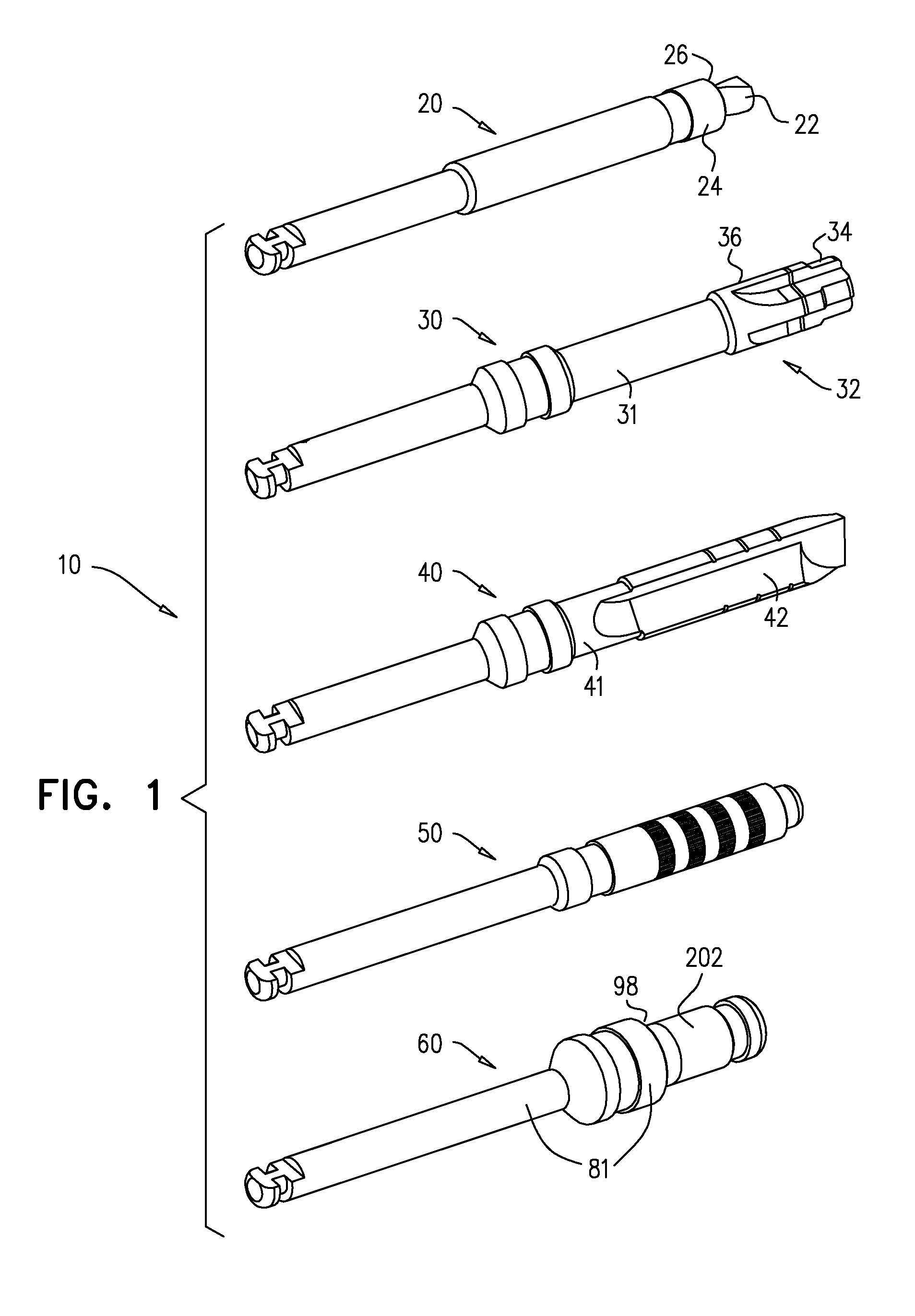
[0124]FIG. 1 is a schematic illustration of a set 10 of dental tools, in accordance with an application of the present invention. Set 10 or a subset thereof may be used to perform the dental procedures described herein, and / or to perform other dental procedures. Set 10 may include one or more of the following dental tools:[0125]a pilot drill 20, which typically comprises a dental twist drill shaped so as to define a stopper 24. Pilot drill 20 is shaped so as to define a proximal shaft 21, a distal bur 22, and stopper 24 proximal to bur 22. Stopper 24 has a greater diameter than that of bur 22, and defines a shoulder 26 comprising a non-cutting distal surface, which prevents advancement of pilot drill 20 beyond a depth equal to a length of bur 22. Typically, bur 22 has a length of between 2 and 5, such as 3 mm;[0126]a counterbore drill 30, which is shaped so as to define a proximal shaft 31 and a distal bur 32. Distal bur 32 includes distal and proximal portions 34 and 36. Proximal p...


PUM


Abstract

A method is provided that includes advancing a drill having a distal end through an occlusal cortex into trabecular bone of an alveolar ridge, and ceasing the advancing of the drill when the distal end of the drill reaches an occlusal surface of a superior cortex of the alveolar ridge. Other embodiments are also described.

Description

FIELD OF THE INVENTION[0001]The present invention relates generally to dental implants and implantation methods, and specifically to minimally-invasive sinus lift implants and implantation methods.BACKGROUND OF THE APPLICATION[0002]Osseointegrated dental implants are typically metallic or ceramic screws that are placed in the jawbone for supporting artificial teeth after the loss of natural teeth. Replacement of the maxillary teeth is often a challenging surgical procedure when the remaining maxillary bone has insufficient height to support the implant. One surgical technique for augmenting the maxillary bone includes injecting a regenerative material, such as autogenic, allogeneic, xenogeneic, or synthetic bone graft, into the vicinity of the maxillary bone. The regenerative material forms additional bone mass that integrates with the existing maxillary bone, providing the necessary alveolar height to support the implant.[0003]Bone augmentation procedures are often surgically diffi...

Claims


Application Information

Patent Timeline
Patent Type & Authority Applications(United States)
IPC IPC(8): A61B17/16
CPCA61C8/0022A61C8/0092
Inventor BETTER, HADARFOSTICK, GIDEONUCHITEL, ILANGROSS, YOSSI
Owner MAXILLENT
Why Eureka
Try Eureka