Fuel supply device for internal combustion engine

a fuel supply device and internal combustion engine technology, applied in the direction of liquid fuel feeders, machines/engines, combustion air/fuel air treatment, etc., can solve the problems of affecting the flow of intake air, reducing the box capacity, and difficult smooth air supply, so as to improve engine performance, smooth intake air flow in the airbox, and simplify the structure inside the airbox

Active Publication Date: 2013-07-25
SUZUKI MOTOR CORP
View PDF7 Cites 8 Cited by
  • Summary
  • Abstract
  • Description
  • Claims
  • Application Information

AI Technical Summary

Benefits of technology

[0012]The present invention was conceived in consideration of the circumstance described above, and an object thereof is to provide a fuel supply device for an internal combustion engine which caus...

Problems solved by technology

Accordingly, there causes a case in which the flow of intake air is disturbed and a pressure drop is caused, making smooth air supply difficult, or the box capacity is reduced due to the many support structures in the airbox.
Furthermore, in the case of arranging the fuel supply piping for the auxiliary injector outside the airbox, there also causes a case in which, for example, since the box capacity is sacrificed or reduced due to the installation outside the airbox, the intake air is easily influenced by the pulsation, and when the amount of intake air is...

Method used


Image

  • Fuel supply device for internal combustion engine
  • Fuel supply device for internal combustion engine
  • Fuel supply device for internal combustion engine

Examples


Embodiment Construction

[0026]Hereinafter, an embodiment of the present invention will be described with reference to the appended drawings. It is further to be noted that terms “upper”, “lower”, “right”, “left” and like terms indicating directions are used herein basically with reference to the illustration of the drawings.

[0027]The embodiment of the present invention is a fuel supply device for an internal combustion engine that is applied to a motorcycle or the like provided with a 4-cycle engine.

[Structure of Motorcycle]

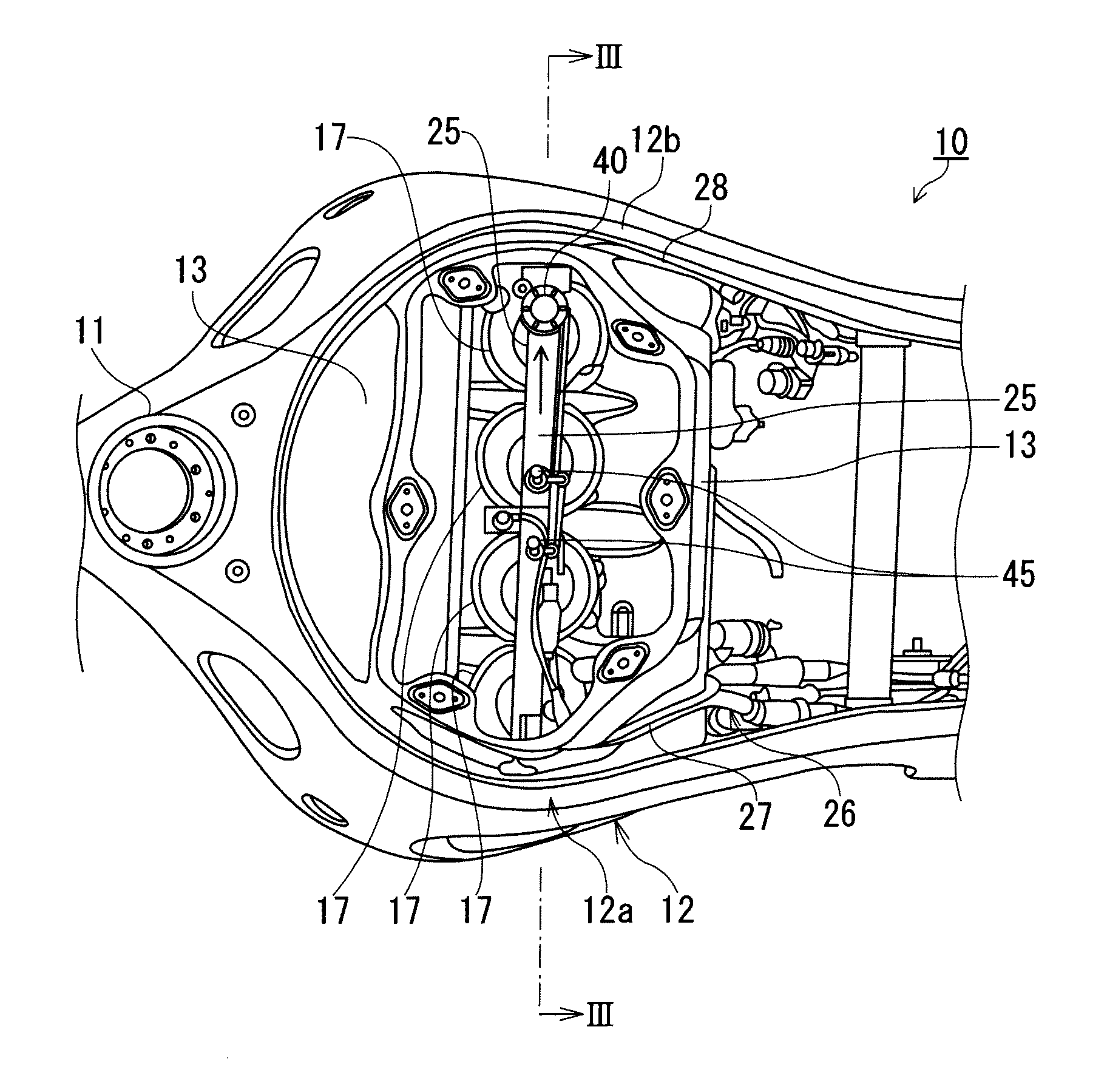
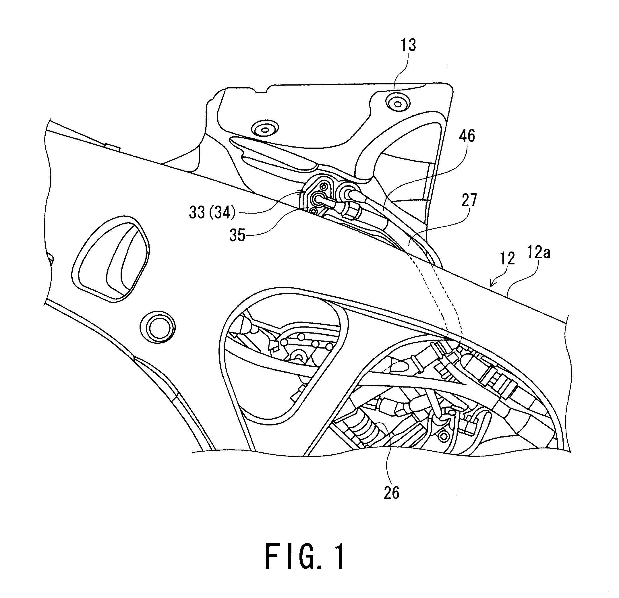
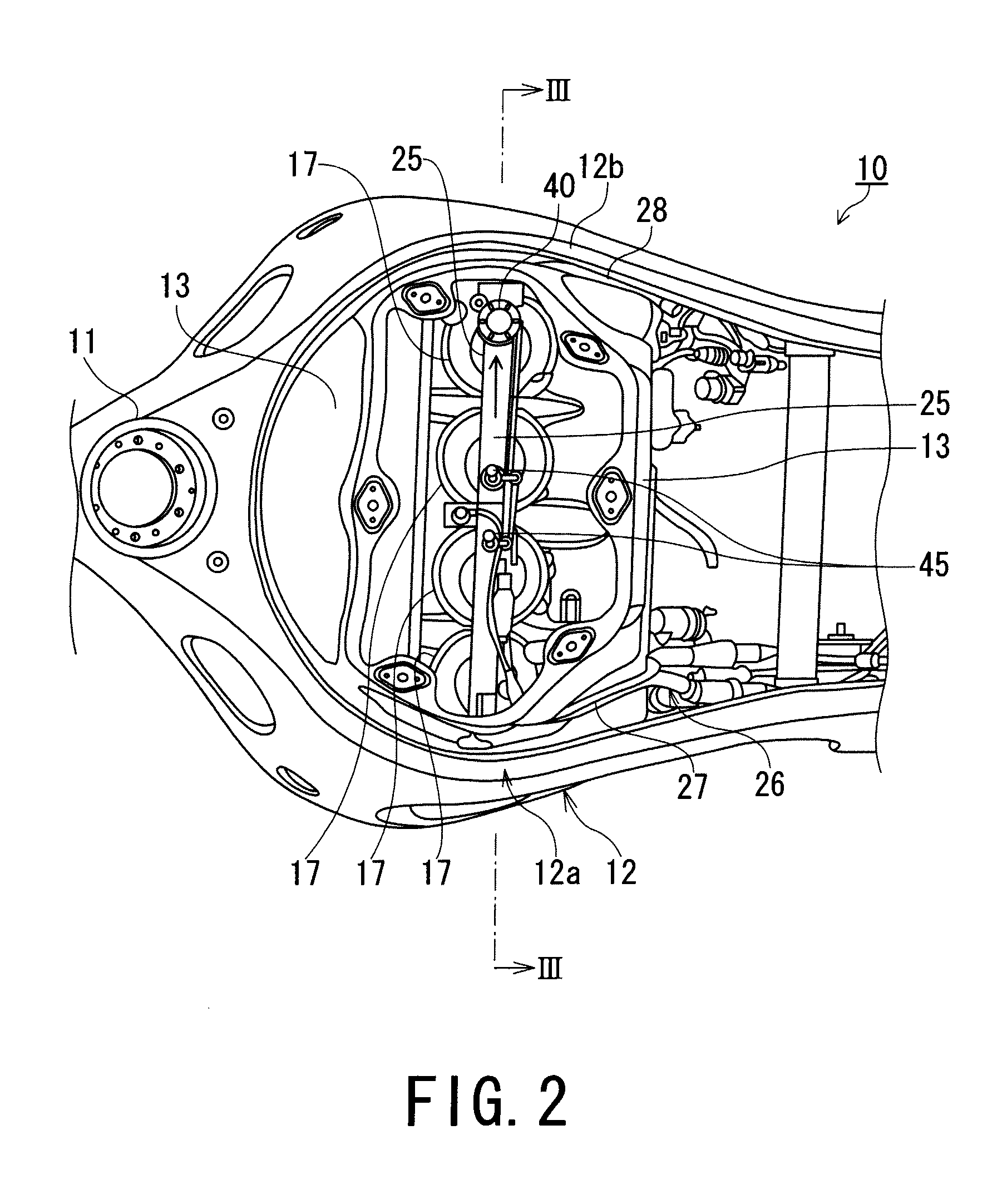
[0028]FIG. 1 is a side view showing an upper front portion of a motorcycle 10 provided with a fuel supply device for an internal combustion engine, and FIG. 2 is a plan view also of the motorcycle.

[0029]The motorcycle 10 is provided with, for example, a 4-cylinder 4-cycle engine, not shown, mounted on a vehicle body frame 12.

[0030]As shown in FIG. 2, the vehicle body frame 12 includes a pair of left and right main frames 12a and 12b divided into left and right parts and extending rearwa...


PUM


Abstract

A fuel supply device for an internal combustion engine including a throttle valve and an airbox is provided with a main injector disposed at a downstream side of the throttle valve, an auxiliary injector disposed at an upstream side of the throttle valve and in the airbox, and a delivery pipe disposed inside the airbox and adopted to supply and distribute a fuel to the auxiliary injector. The delivery pipe has both ends which are supported on two side walls of the airbox.

Description

PRIORITY CLAIM[0001]This patent application claims priority to Japanese Patent Application No. 2012-011287, filed 23 Jan. 2012, the disclosure of which is incorporated herein by reference in its entirety.BACKGROUND OF THE INVENTION[0002]1. Field of the Invention[0003]The present invention relates to a fuel supply device for an internal combustion engine, in which injectors are disposed at a downstream side and an upstream side of a throttle valve, respectively.[0004]2. Related Art[0005]With respect to a 4-cycle engine provided in a motorcycle or the like, there is a fuel supply device or apparatus that uses two injectors per one cylinder.[0006]A fuel supply device, for an internal combustion engine, that includes a main injector at the downstream side of a throttle valve provided to a throttle body and an auxiliary injector at the upstream side of the throttle valve so as to supply fuel to both of the injectors from a fuel supply piping, is known from, for example, Patent Document 1...

Claims


Application Information

Patent Timeline
IPC IPC(8): F02M35/10
CPCF02M63/0275F02M35/10216F02M51/005F02M61/14F02M35/10039F02M69/044F02M69/462F02M69/465F02M69/54F02M69/043
Inventor UCHIYAMA, TATSUSHI
Owner SUZUKI MOTOR CORP
Why Eureka
Try Eureka