Interface unit, measurement system and a method in an interface unit

US20130225941A1Active Publication Date: 2013-08-29ST JUDE MEDICAL COORDINATION CENT

Image

  • Interface unit, measurement system and a method in an interface unit
  • Interface unit, measurement system and a method in an interface unit
  • Interface unit, measurement system and a method in an interface unit

Examples


Embodiment Construction

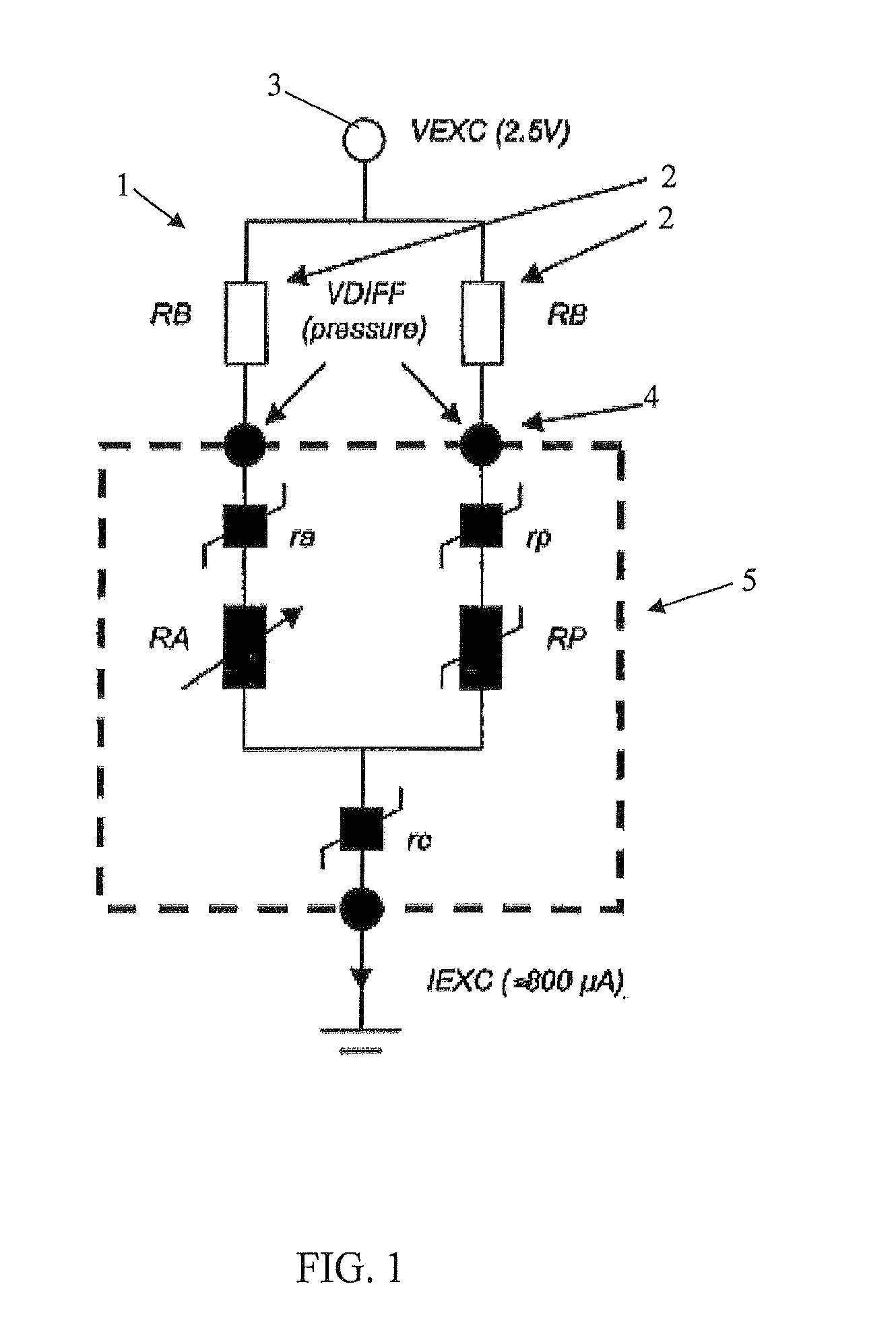
[0030]FIG. 1 shows a known sensor interface circuitry 1 using a matched resistor pair 2 in a Wheatstone bridge-type circuit excited from a constant voltage source 3. The sensor interface circuitry 1 is adapted to be arranged in for example a transceiver unit adapted to be connected, via connection points 4, to the proximal end of a sensor wire 5 (schematically illustrated in FIG. 1) provided, at its distal end, with a sensor to measure a variable in a living body. The Wheatstone bridge-type circuit comprises a matched resistor pair 2 (RB, RB), an active resistor RA and a passive resistor RP. The sensor element comprises piezoresistive elements mounted on a membrane and is connected to the Wheatstone bridge-type circuit, shown in FIG. 1. When the sensor element is placed in fluid communication within a body cavity, a certain pressure exerted on the membrane from the surrounding medium will correspond to a certain stretching or deflection of the membrane and thereby to a certain resis...


PUM


Abstract

The present invention relates to an extracorporeale interface unit (8), for an intravascular measurement system for measuring a physiological, or other, variable in a living body, being adapted to generate a sensor signal in response of said variable. The interface unit (8) comprises a sensor interface circuitry (6) adapted to interface a sensor wire configured to be inserted into the living body and provided with one or many sensor element(s) at its distal region. The sensor interface circuitry (6) further comprises a measurement unit (9) adapted to generate the measured data of the variable as a sensor signal. The sensor interface circuitry (6) comprises two current source units (CSU1, CSU2) adapted to energize the sensor element(s) via at least two connection points (CP1, CP2, . . . CPn), and a switching unit (10), wherein the switching unit (10) is adapted to alternately switch connection between the current source units (CSU1, CSU2) and at least two of the connection points (CP1, CP2, . . . CPn), using a preset switching frequency having essentially the same connection time period (Tc) for each connection. The measurement unit (9) is adapted to determine a sensor variable value (Vdiff) related to the variable at two of the connection points (CP1, CP2, . . . CPn). The present invention further relates to a measurement system (12) comprising said extracorporeale interface unit (8) and a method in said interface unit.

Description

FIELD OF THE IVENTION[0001]The present invention relates to an interface unit, a measurement system comprising said interface unit, and a method in an interface unit according to the preamble of the independent claim.BACKGROUND[0002]In many medical procedures, various physiological conditions present within a body cavity need to be monitored. These physiological conditions are typically physical in nature—such as pressure, temperature, rate-of-fluid flow, and provide the physician or medical technician with critical information as to the status of a patient's condition.[0003]One device that is widely used to monitor conditions is the blood pressure sensor. A blood pressure sensor senses the magnitude of a patient's blood pressure, and converts it into a representative electrical signal that is transmitted to the exterior of the patient.[0004]In the prior art, it is known to mount a sensor at a distal portion of a so-called sensor wire and to position the sensor by using the sensor w...

Claims


Application Information

Patent Timeline
29 Aug 2013
Publication
US20130225941A1
IPC
A61B5/00
CPC
A61B5/6851; A61B5/0002; A61B5/4836; A61B5/6876; A61B2560/045; A61N1/00; A61B5/0215; A61B5/7225
Inventors
SAMUELSSON, MAGNUS