Electrical ground fault protection device

a technology of ground fault protection and electric ground, which is applied in the direction of electrical cables, earth connection, electrical equipment, etc., can solve the problems of less than desired or optimal functional effectiveness of devices, difficulty in earth rod installation, and risk of personal injury and expensive utility repair costs, so as to facilitate the installation of gfp devices, improve the conductivity between them, and soften the soil

Active Publication Date: 2013-09-05
R U GROUNDED ENERGY
View PDF2 Cites 5 Cited by
  • Summary
  • Abstract
  • Description
  • Claims
  • Application Information

AI Technical Summary

Benefits of technology

[0011]To ground a structure or equipment component, a suitable conductive cable is extended between the structure or component and the GFP device's grounding terminal means and electrically connected to both, by any suitable means (such as conventional alligator clips). In situations where conductivity between the electrodes and the ground is less than optimal, due to the particular nature and characteristics (including moisture content) of the soil in which the electrodes have been or are to be installed, water may be added to the GFP device's reservoir such that it will drip into the soil below the GFP device, thereby moistening the soil around the electrodes and improving conductivity therebetween. The addition of water also softens the soil and thereby facilitates installation of the GFP device by reducing physical resistance to penetration of the electrodes. Water may be added periodically to the reservoir as desired or appropriate to maintain or extend the beneficial effects of adding water to the soil in the vicinity of the GFP device.
[0012]When the GFP device is no longer needed (such as in temporary installations), it is a simple matter for workers to lift the device out of the ground (using pry bars or other implements if necessary), and then to manually transport the device (using the integral handles, if provided) away from the site as appropriate.
[0013]In one alternative embodiment, the main body of the GFP device comprises a solid member (e.g., a solid plate) with top and bottom surfaces and not including a water reservoir. In a further alternative embodiment, the main body comprises a hollow member that is sealed but does not serve as a water reservoir; in this embodiment, the hollow or tubular configuration of the main body is selected for other design purposes (such as to provide desired levels of structural strength and rigidity while minimizing weight).

Problems solved by technology

The installation of driven or augered earth rods typically entails the use of specialized rod-driving or augering equipment, and even with the use of such equipment earth rod installation can be difficult due to soil conditions (for example, rock formations close to surface).
Even when soil conditions are readily conducive to earth rod installation, the presence of buried utilities (e.g., gas lines, electrical power lines, water lines) can give rise to the risk of personal injury and expensive utility repair costs should such buried utilities be contacted or penetrated by earth rods during the rod installation process.
These latter risks can be mitigated or avoided by the use of ground mats not having ground-penetrating elements, but such devices may have less than desired or optimal functional effectiveness.

Method used


Image

  • Electrical ground fault protection device
  • Electrical ground fault protection device
  • Electrical ground fault protection device

Examples


Embodiment Construction

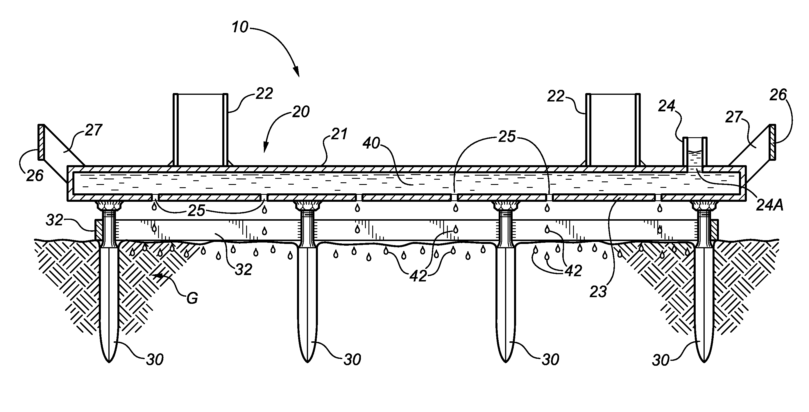
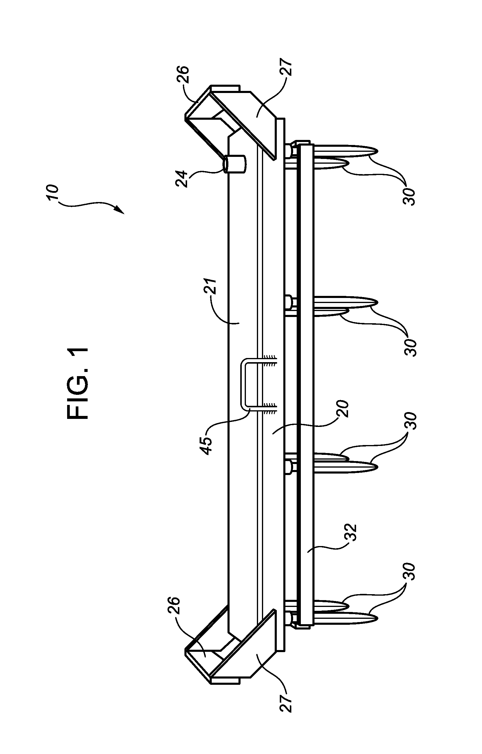
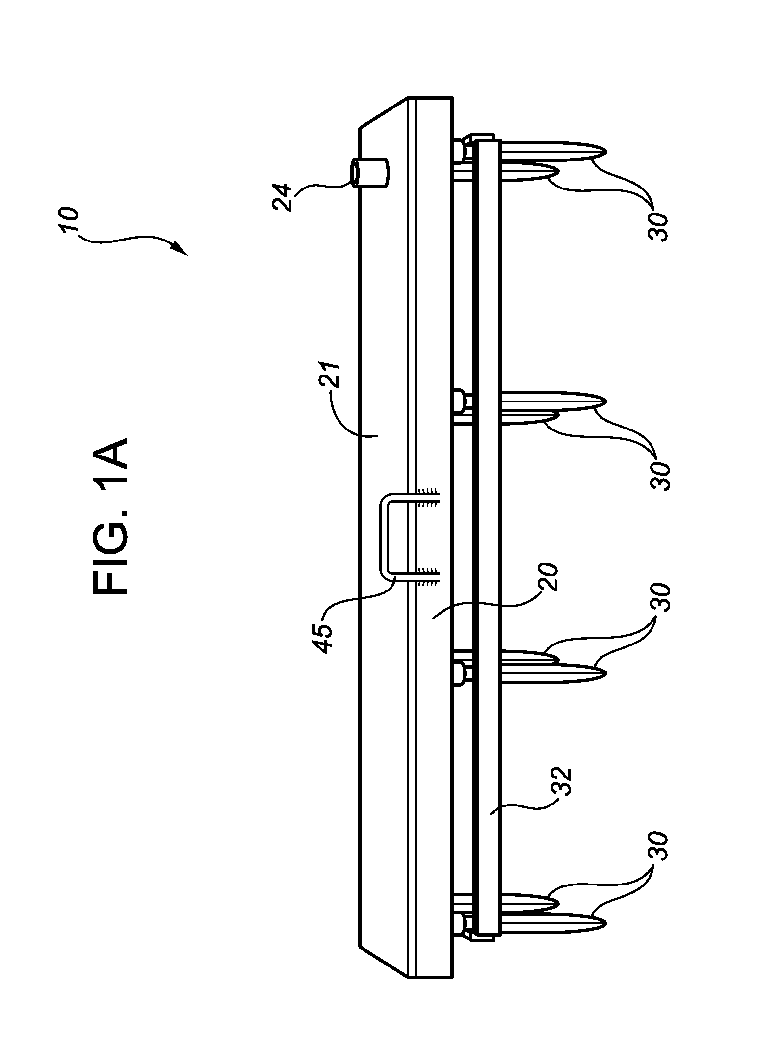
[0025]The Figures illustrate embodiments of a ground fault protection (GFP) device 10 in accordance with the present disclosure. In the illustrated embodiments, GFP device 10 comprises a hollow main body 20 made from an electrically-conductive material. Main body 20 has a top plate 21, a top surface 21A, a bottom plate 23, a bottom surface 23A, and defines an internal reservoir 40. A suitable reservoir inlet port 24 (shown by way of non-limiting example as comprising a pipe stub and an associated opening 24A in top plate 21) is provided to allow reservoir 40 to be filled with water. Bottom plate 23 has a plurality of drainage ports 25, which may be provided in any suitable or desired pattern.

[0026]A plurality of downwardly-extending, ground-penetrating electrodes 30 are connected to main body 20 by electrically-conductive means (such as welding or bolting). In the illustrated embodiment, main body 20 is of rectangular configuration, and electrodes 30 are arranged in a rectangular pa...


PUM


Abstract

A ground fault protection device includes an electrically-conductive main body having downwardly-extending, ground-penetrating electrodes configured for minimal ground penetration. The device has one or more grounding terminals for connection of grounding cables, and may have handles for manual transportation. The device may be installed at a desired field location by applying downward force to the device to press the electrodes into the earth, thereby establishing an electrical connection between the grounding terminals and the ground via the main body and the electrodes. Grounding cables may then be connected between the grounding terminals and structures or equipment requiring grounding. Optionally, the main body may define a reservoir having a plurality of drainage ports. The reservoir may be filled with water, which will drip through the drainage ports and moisten the soil surrounding the electrodes, thereby decreasing the soil's electrical resistance and improving electrical conductivity between the electrodes and the soil.

Description

FIELD OF THE DISCLOSURE[0001]The present disclosure relates in general to electrical ground fault protection (GFP) systems, chiefly but not solely for use in temporary applications. In particular, the disclosure relates to GFP systems and apparatus for use in conjunction with construction, well-drilling, remote dwellings, and other applications where portable electrical generation facilities are employed, and more particularly in applications where it is necessary or desirable to provide ground fault protection for equipment and structures with minimal ground disturbance or ground penetration, and where removal and recovery of GFP devices may be necessary or desirable.BACKGROUND[0002]Known ground fault protection (GFP) technologies commonly rely on electrically-conductive elements (i.e., electrodes) driven, augered, or buried a significant depth into the ground in order to effectively conduct electrical current into the ground. Such conductive elements, commonly known as earth rods ...

Claims


Application Information

Patent Timeline
Patent Type & Authority Applications(United States)
IPC IPC(8): H02G13/00
CPCH01R4/66H02G13/40
Inventor MUNDLE, TERRY D.
Owner R U GROUNDED ENERGY
Why Eureka
Try Eureka