Impactor

a technology of impactors and implants, applied in the field of impactors, can solve problems such as loss of implant stability within the cavity, and achieve the effect of preventing or reducing the likelihood of over-insertion of implants

Inactive Publication Date: 2013-10-10
SI BONE INC
View PDF3 Cites 55 Cited by
  • Summary
  • Abstract
  • Description
  • Claims
  • Application Information

AI Technical Summary

Benefits of technology

[0009]This application relates generally to impactors. More specifically, this application relates to impactors used in medical procedures such as bone fixation or fusion. In some embodiments, the impactors include features that prevent or reduce the likelihood of over-insertion of an implant within a bone cavity.

Problems solved by technology

Over-insertion of the implant caused by striking the implant with too much force or striking the implant too many times can cause a variety of problems, such as loss of implant stability within the cavity.

Method used


Image

  • Impactor
  • Impactor
  • Impactor

Examples


Embodiment Construction

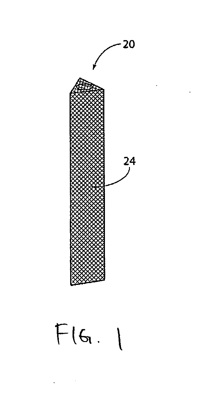
[0046]Elongated, stem-like implant structures 20 like that shown in FIG. 1 make possible the fixation of the SI-Joint (shown in anterior and posterior views, respectively, in FIGS. 3 and 4) in a minimally invasive manner. These implant structures 20 can be effectively implanted through the use a lateral surgical approach. The procedure is desirably aided by conventional lateral, inlet, and outlet visualization techniques, e.g., using X-ray image intensifiers such as a C-arms or fluoroscopes to produce a live image feed, which is displayed on a TV screen.

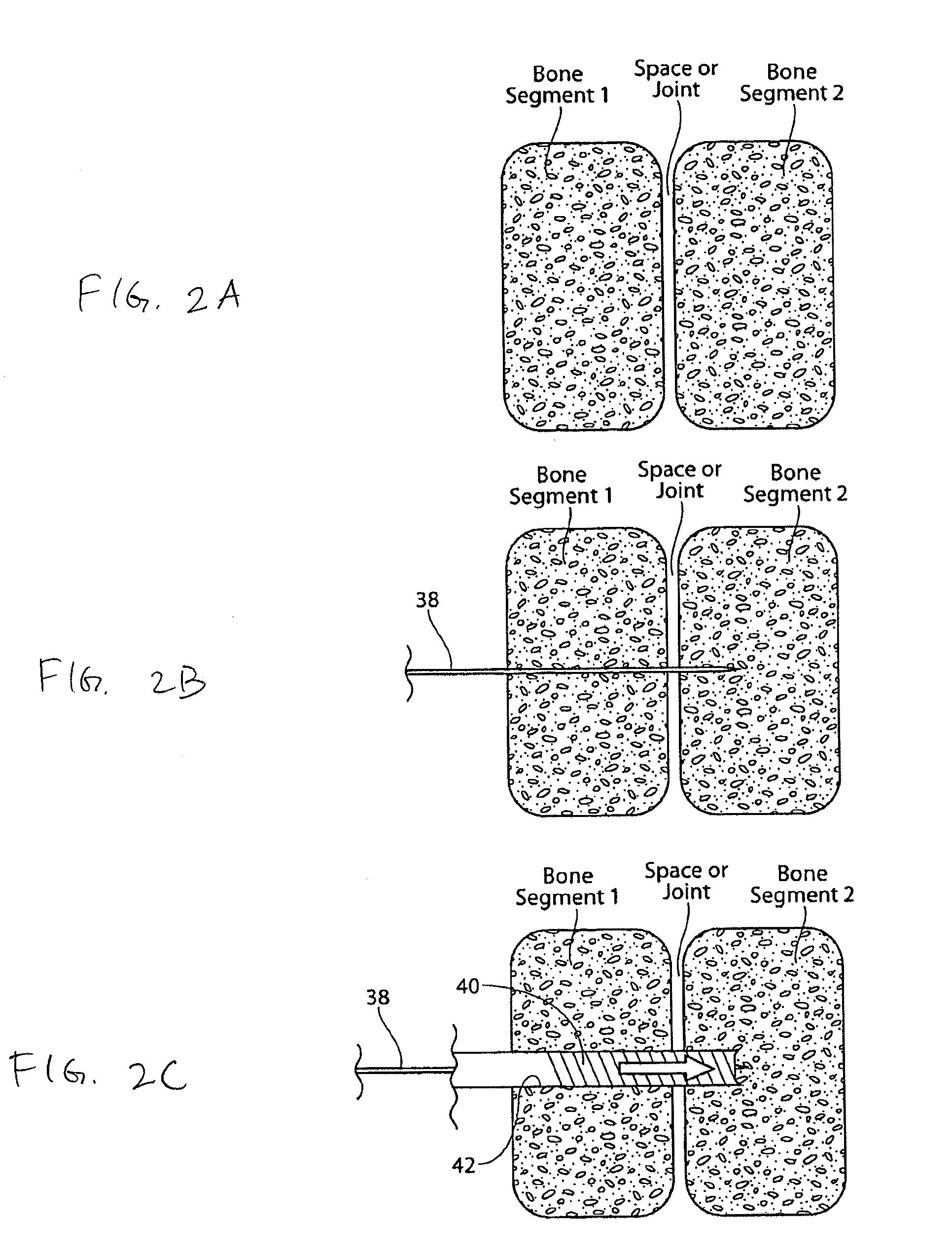
[0047]In one embodiment of a lateral approach (see FIGS. 5, 6, and 7A / B), one or more implant structures 20 are introduced laterally through the ilium, the SI-Joint, and into the sacrum. This path and resulting placement of the implant structures 20 are best shown in FIGS. 6 and 7A / B. In the illustrated embodiment, three implant structures 20 are placed in this manner. Also in the illustrated embodiment, the implant structures 20 are...


PUM


Abstract

This application relates generally to impactors. More specifically, this application relates to impactors used in medical procedures such as bone fixation or fusion. In some embodiments, the impactors include features that prevent or reduce the likelihood of over-insertion of an implant within a bone cavity.

Description

CROSS REFERENCE TO RELATED APPLICATIONS[0001]This application claims priority to U.S. Provisional Application No. 61 / 609,002, filed Mar. 9, 2012, titled “IMPACTOR,” which is hereby incorporated by reference in its entirety.INCORPORATION BY REFERENCE[0002]All publications and patent applications mentioned in this specification are herein incorporated by reference to the same extent as if each individual publication or patent application was specifically and individually indicated to be incorporated by reference. For example, this application incorporates by reference in their entireties U.S. Patent Publication No. 2011 / 0087294 and U.S. Patent Publication No. 2011 / 0118785.FIELD[0003]This application relates generally to impactors. More specifically, this application relates to impactors used in medical procedures such as bone fixation or fusion.BACKGROUND[0004]Many types of hardware are available both for the fixation of bones that are fractured and for the fixation of bones that are ...

Claims


Application Information

Patent Timeline
Patent Type & Authority Applications(United States)
IPC IPC(8): A61B17/88
CPCA61B17/8872A61B17/92A61B2019/306A61B17/846A61B2017/922A61B17/68A61B2090/036
Inventor MAULDIN, RICHARD G.PATEL, VIKAS V.YERBY, SCOTT A.SAND, PAUL
Owner SI BONE INC
Why Eureka
Try Eureka