Viscous liquid dispensing pump

a liquid dispensing pump and viscous technology, applied in the field of pumps, can solve problems such as air venting back through the self-sealing valve, and may aris

Inactive Publication Date: 2006-10-19
KIMBERLY-CLARK WORLDWIDE INC
View PDF7 Cites 20 Cited by
  • Summary
  • Abstract
  • Description
  • Claims
  • Application Information

AI Technical Summary

Problems solved by technology

A problem may arise, however, if the dispensing pump disclosed in WO02 / 49490 is used to receive liquid from an unvented reservoir.
Such contact is undesirable as it may lead to contamination by airborne contaminants.
This means that when the pressure in the reservoir falls sufficiently low, air will vent back through the self-sealing valve which, as explained above, is undesirable.

Method used


Image

  • Viscous liquid dispensing pump
  • Viscous liquid dispensing pump
  • Viscous liquid dispensing pump

Examples


Embodiment Construction

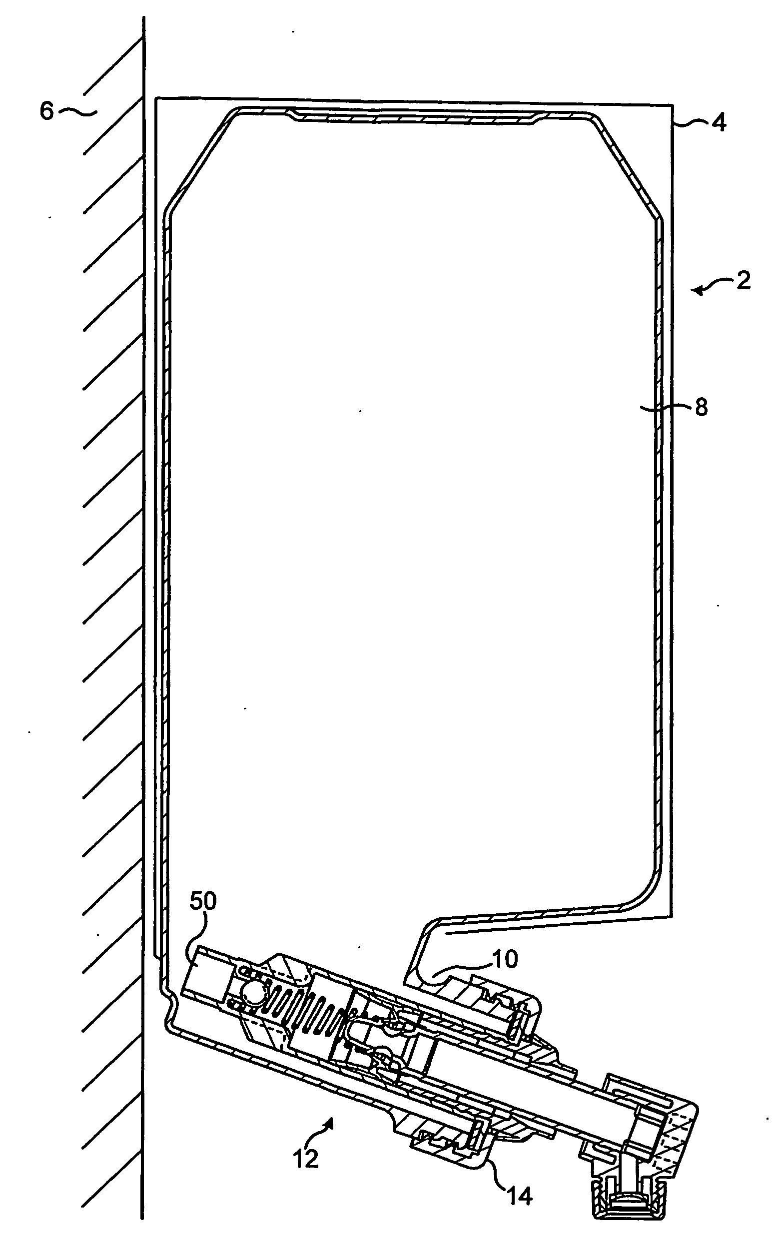
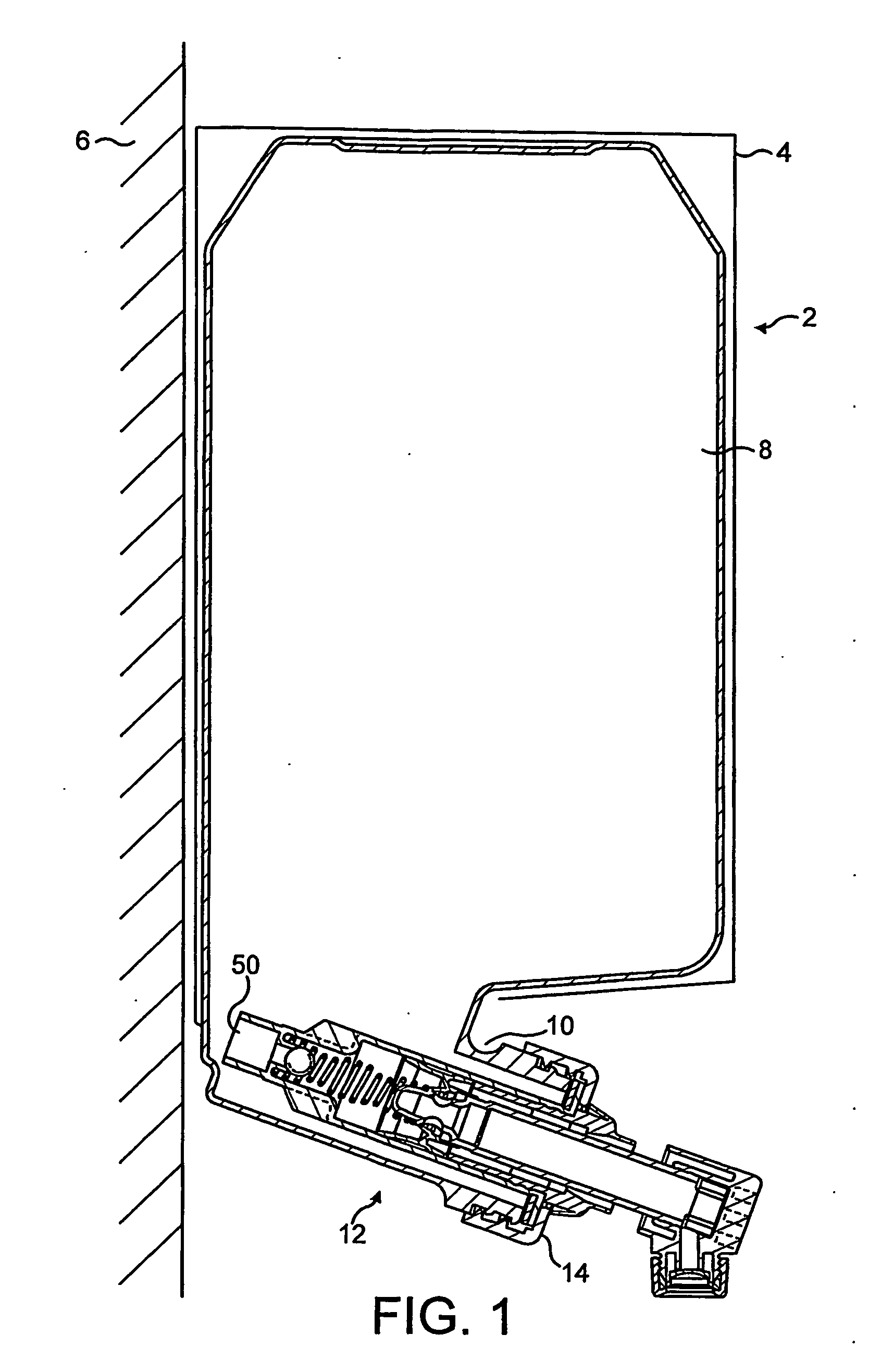
[0034] With reference to FIG. 1, a dispenser 2 for dispensing viscous liquid such as soap, shampoo or lotion comprises a housing 4 mounted to a support structure such as a wall 6.

[0035] The housing 4 houses a collapsible plastic reservoir 8 containing the liquid to be dispensed. The reservoir 8 is formed with an integral outlet 10 in which a dispensing pump 12 in accordance with the invention is mounted through a screw cap 14.

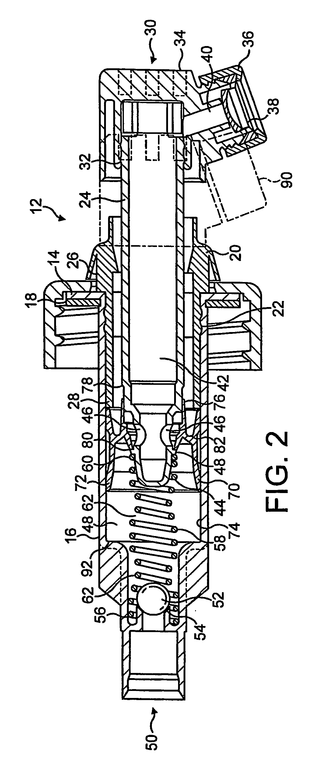
[0036] The pump 12 will be described in greater detail with reference to FIG. 2.

[0037] The dispensing pump 12 comprises a moulded plastics cylinder 16 which is provided with a retaining flange 18 at one end, for engagement with the mounting cap 14 a plastics collar 20 snap fits into grooves 22 provided adjacent the flange 18 on the cylinder 16.

[0038] The collar 20 slidably receives a reciprocating dispensing piston 24. The dispensing piston 24 is formed with ribs 26 which engage the inner wall 28 of the collar 20.

[0039] A self-sealing valve unit 30 is moun...


PUM


Abstract

A dispensing pump (12) for a viscous liquid comprises a cylinder (16), a piston (24) mounted for reciprocation within said cylinder (16), an inlet (50) for admitting liquid to be dispensed into said cylinder (16) and a ball check valve (52) arranged selectively to open and close said inlet opening. The ball valve (52) is retained in position by a spring (58) having a variable diameter. The piston (24) has a dispensing passage (40) in fluid communication with said cylinder (16) and with a self sealing dispensing valve (38). The pump (12) further comprises a sliding cut-off valve (70) arranged selectively to open and close fluid communication between the piston dispensing passage (40) and the cylinder (16) as the piston (24) reciprocates within the cylinder (16).

Description

FIELD OF THE INVENTION [0001] The present invention relates to pumps for dispensing viscous liquids such as soap, shampoo, lotion and food products. BACKGROUND OF THE INVENTION [0002] Various viscous liquid dispensers are known. The dispenser typically comprises a reservoir for containing the product to be dispensed and a dispensing pump for dispensing the product from the reservoir. [0003] Such dispensers are commonly used in public rest rooms, where they are typically wall mounted. In such dispensers the dispensing pump is usually provided at the lower part of the dispenser, below the reservoir. The reservoir may itself be attached to a fixed surface or be housed in a housing which is so mounted. A pump actuator may be provided on the dispenser housing to actuate the dispensing pump. The liquid reservoir may be vented or unvented. Examples of such dispensers are disclosed in U.S. Pat. No. 5,556,005 and International Patent Application WO02 / 49490. [0004] In other dispensers, more t...

Claims


Application Information

Patent Timeline
Patent Type & Authority Applications(United States)
IPC IPC(8): G01F11/00A47K5/12B05B11/00
CPCA47K5/1204B05B11/3023B05B11/0043A47K5/1205B05B11/026B05B11/1023B65D47/00B65D83/00B05B11/00
Inventor POWLING, DAVID JAMES SEALYZUBILLAGA, JESUS-MARIA
Owner KIMBERLY-CLARK WORLDWIDE INC
Why Eureka
Try Eureka