Smartphone with front camera and maximized display screen

a front-facing camera and display screen technology, applied in the field of smart phones, can solve the problems of reducing the light sensitivity of the front-facing camera located beneath the display screen, clouding the resultant picture, and limiting the transmission efficiency of unpolarized light, so as to maximize the remaining screen area

Inactive Publication Date: 2018-08-02
INODYN NEWMEDIA
View PDF5 Cites 40 Cited by
  • Summary
  • Abstract
  • Description
  • Claims
  • Application Information

AI Technical Summary

Benefits of technology

[0014]Aspects of the present disclosure are directed to mobile electronic devices with a display screen and at least one front-facing camera, optical sensor, and / or emitter, such as smartphones or phablets. In embodiments of the present invention, a smartphone may have very thin borders at the top and / or bottom edge of the display screen as well as at the left- and right-hand edges of the display screen. To accommodate an optical sensor, such as a front camera, in spite of a border that is too thin for the optical sensor (e.g., camera module and lens), at least one corner of the display panel may be cut out such that a recess is created. An optical sensor and / or emitter or the lens of a front camera may be disposed at the location of the recess or cutout. Optionally, in some embodiments, the recess or cutout may have a convex shape for the most part, thereby maximizing the remaining screen area.

Problems solved by technology

However, depending on the display technology of the screen (e.g., LCD, OLED, Micro-LED, etc.), small opaque or semi-transparent structures that may be necessary for the operation of the display screen may blur or cloud the resulting picture of the front-facing camera, because the light path must pass through the display screen.
Furthermore, LCD panels often also require removing a diffuser layer to adapt them for use as transparent displays, and the polarizing filters of the LCD panels inherently limit the transmission efficiency of unpolarized light.
This may reduce the light sensitivity of a front-facing camera located beneath the display screen, especially in low-light conditions.
The disadvantage of this solution is that the upper status bar (e.g., a text line with the time of day and icons for signal strength, battery level, cellular network type, etc.) is interrupted by the notch in the middle.

Method used


Image

  • Smartphone with front camera and maximized display screen
  • Smartphone with front camera and maximized display screen
  • Smartphone with front camera and maximized display screen

Examples


Embodiment Construction

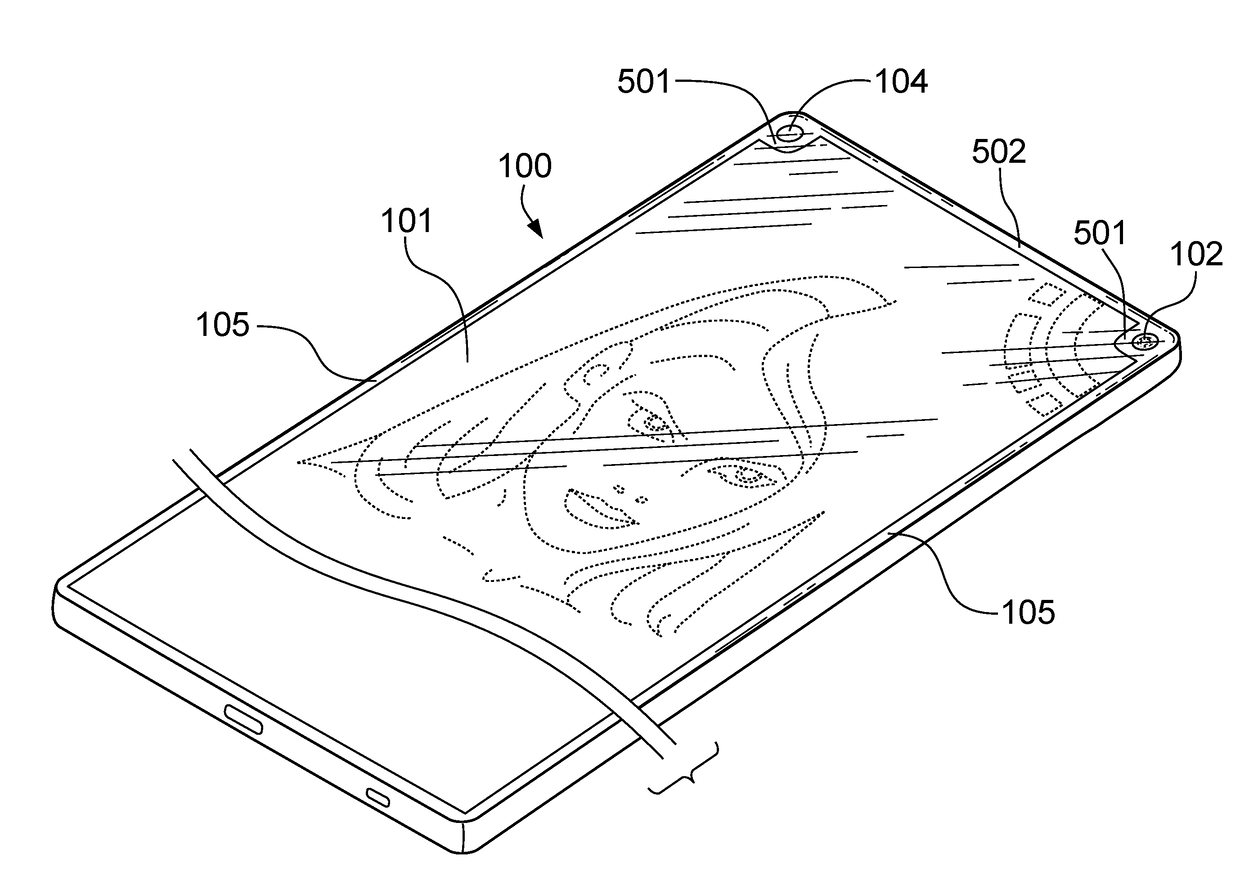
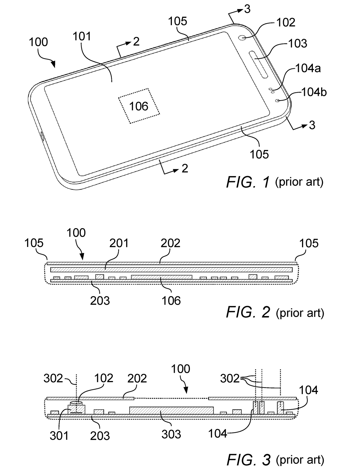
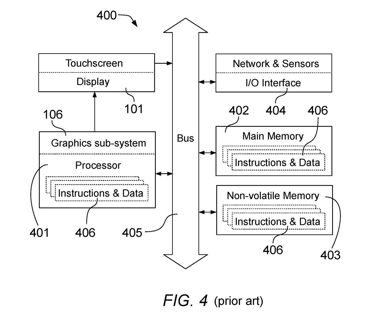
[0046]FIG. 1 (labeled “prior art”) shows a conventional smartphone 100 as an example of a mobile electronic device. The drawing illustrates a display screen 101 with touchscreen functionality, the lens 102 of a front-facing camera, an earpiece 103 (ear speaker for telephone calls), and optical sensors and / or emitters 104. An optical sensor 104a may be, for instance, a combined proximity and light sensor and an optical emitter 104b may be, for instance, a flash LED or an infrared (IR) LED to illuminate the face of the user. Alternatively, the optical emitter 104b may be a status LED that indicates operating states, such as “on / off” or “charging battery.” A graphics sub-system 106 (integrated into the smartphone 100 and shown in dotted lines in FIG. 1) is responsible for generating the screen content displayed on the display screen 101.

[0047]As can be seen in FIG. 1, conventional smartphones 100 typically feature a thin border 105 at the left and right edge of the display screen 101. ...


PUM


Abstract

A smartphone device may have thin borders at the left, right, top, and/or bottom edges of the display screen. To accommodate, e.g., a front camera in spite of a border that is too thin for a camera module and lens, at least one corner of the display may be cut out. Optical sensor(s), emitter(s), or the lens of a front camera may be disposed at the location(s) of the cutout(s). A wide-screen movie may be displayed in letterbox mode with horizontal bars above and/or below the movie, wherein the cutout(s) are located, at least partially, in the region(s) of the horizontal bars, thereby avoiding that larger parts of the movie are hidden by the cutout(s). In other embodiments, an uninterrupted status bar may be displayed between a cutout in the upper-left corner and a cutout in the upper-right corner of the display.

Description

CROSS-REFERENCE TO RELATED APPLICATIONS[0001]This application is a continuation of U.S. application Ser. No. 29 / 539,390, filed Sep. 14, 2015. The benefit of the above prior application is claimed and the entire disclosure of the prior application, including the unabridged description, as originally filed on Sep. 14, 2015, is expressly incorporated herein by reference.TECHNICAL FIELD[0002]The present invention relates to smartphones and, in particular, to methods and systems that maximize the display screen of a smartphone while providing a high-quality, front-facing camera.BACKGROUND OF THE INVENTION[0003]Common smartphones, phablets, or comparable mobile electronic devices contain a front-facing camera placed on the front side of the mobile electronic devices. The front side of the mobile electronic devices also contains a display screen, using a display technology such as liquid-crystal display (LCD) or active-matrix organic light-emitting diode (AMOLED).[0004]For example, the dis...

Claims


Application Information

Patent Timeline
Patent Type & Authority Applications(United States)
IPC IPC(8): H04M1/02
CPCH04M1/0266H04M1/0264H04M2250/12G06F1/1686G09G3/2092G09G2340/04G09G2340/145G09G2354/00G06F1/1626G06F1/1637H10K59/40G02F1/13338G06F1/1605G06F3/041
Inventor PANTEL, LOTHAR
Owner INODYN NEWMEDIA
Why Eureka
Try Eureka