Electric vehicle

a technology of electric vehicles and vehicles, applied in the direction of electric devices, process and machine control, instruments, etc., can solve the problems of affecting the vehicle's travel performance, and affecting the stability of the vehicle, so as to simplify the configuration or construction, and improve the accuracy of determining

Inactive Publication Date: 2013-12-26
NTN CORP
View PDF3 Cites 16 Cited by
  • Summary
  • Abstract
  • Description
  • Claims
  • Application Information

AI Technical Summary

Benefits of technology

[0014]A wheel bearing unit 4 as well as a load sensor 41 configured to determine the vertical load component acting on the drive wheel 2 may further be provided, wherein the load sensor 41 may be mounted on the wheel bearing unit 4. Such a configuration of a load sensor 41 being mounted on the wheel bearing unit 4 enhances the accuracy in determining the vertical load component Fz acting on the drive wheel 2, thus enabling more proper determination of the maximum acceptable torque Tmax. Such a configuration can also realize a smaller configuration to determine a load. Furthermore, such a configuration allows for pre-mounting the wheel bearing unit 4 with a load sensor 41, thus providing a load sensor-equipped wheel bearing unit. This can eliminate the step of mounting a load sensor 41 on the wheel bearing unit 4 in an assembly process of the vehicle.
[0015]The motor torque command value limiter 47 may comprise a torque limiter. A torque limiter can achieve, with a simplified configuration or construction, proper limitation of a motor torque command value.

Problems solved by technology

However, such highly responsive motor(s) may undesirably cause sudden increase of rotation of tire(s) when the tire(s) lose(s) contact with a road surface due to, for example, slip of the tire(s).
Hence, sudden increase of rotation of a motor that may occur in response to slip may jeopardize the stable travel of a vehicle.
Thus, limiting a motor torque command value in a uniform fashion throughout different conditions may often result in unnecessary limitation of torque, thus jeopardizing the travel performance of the vehicle.

Method used


Image

  • Electric vehicle
  • Electric vehicle
  • Electric vehicle

Examples


Embodiment Construction

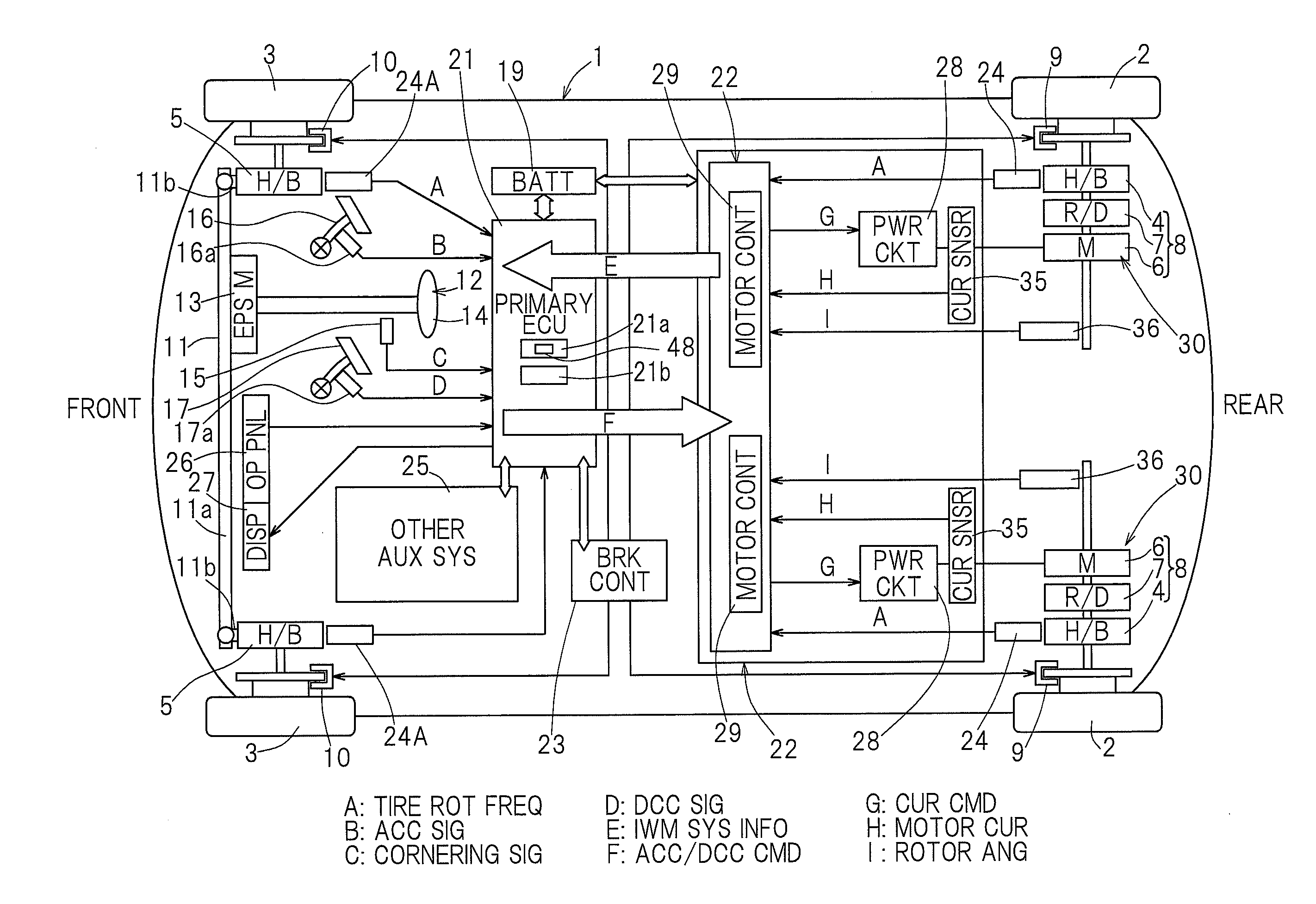
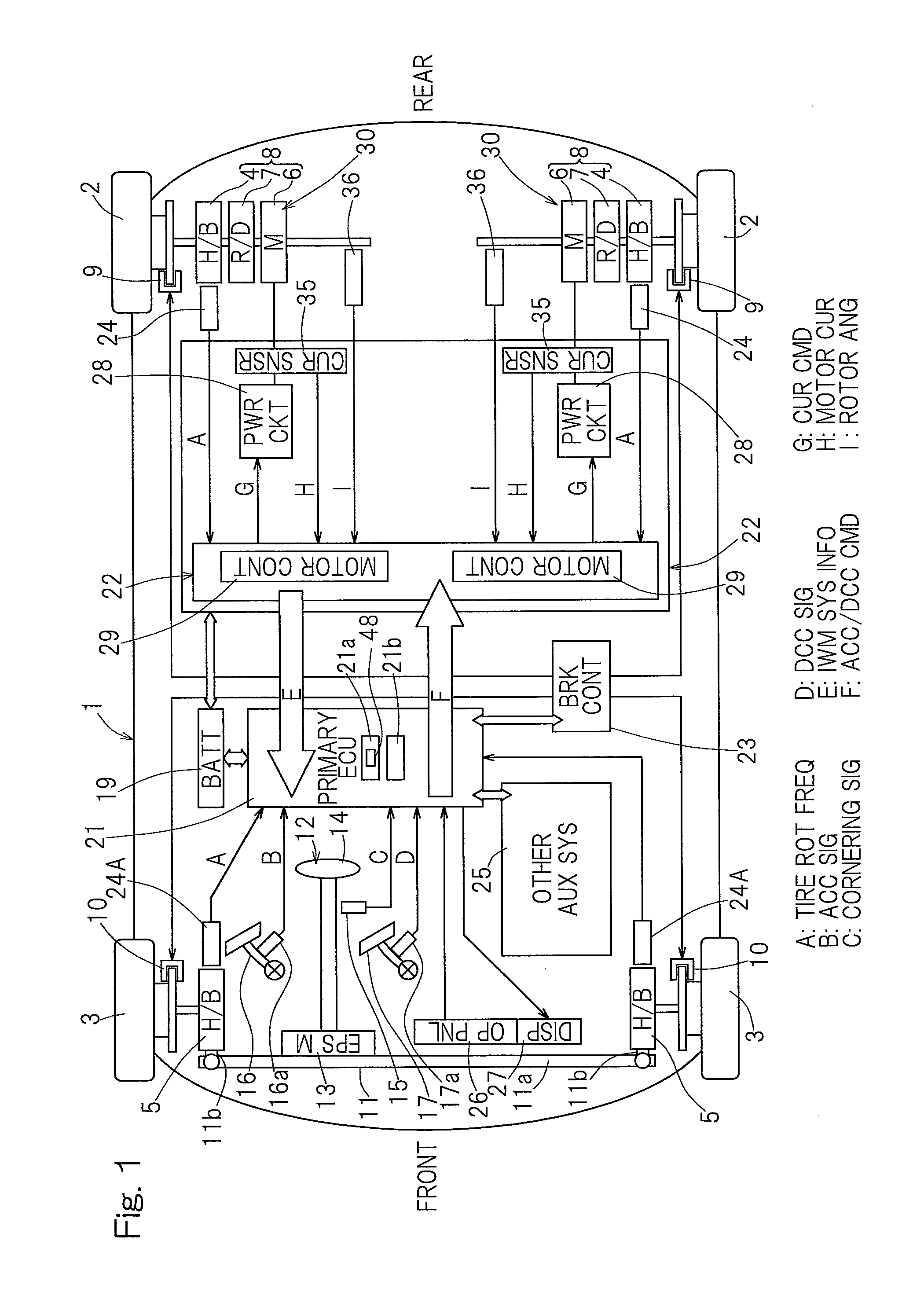
[0033]An embodiment of the present invention will now be described in connection with FIG. 1 to FIG. 12. The illustrated electric vehicle is a four-wheel vehicle such as shown in FIG. 1 that includes a vehicle body 1 with left and right rear wheels and left and right front wheels, with the rear wheels being drive wheels 2 and the front wheels being steered driven wheels 3. The drive wheels 2 and the driven wheels 3, both equipped with tires, are supported by the vehicle body 1 via respective wheel bearing units 4, 5. In FIG. 1, the wheel bearing units 4, 5 are labeled with “H / B” which is an abbreviation for hub bearing. The left and right drive wheels 2, 2 are driven by respective independent traction motor units 6, 6. Rotation of a motor unit 6 is transmitted via a reducer unit 7 and a wheel bearing unit 4 to a wheel 2. The motor unit 6, the reducer unit 7 and the wheel bearing unit 4 are integrally assembled with each other to form an in-wheel motor drive system 8. The in-wheel mo...


PUM


Abstract

An electric vehicle includes a slip ratio estimator that estimates a slip ratio based on rotational frequencies of respective driven and drive wheels. The vehicle also includes a disturbance observer that determines an estimate of a torque attributable to external force. The vehicle also includes an estimator that may estimate an entire torque to the drive wheel, based on a motor torque command value and the estimate of torque. The vehicle also includes an estimator that estimates a coefficient of friction between a road surface and a tire, based on the entire torque and the slip ratio. The vehicle also includes a determiner that determines a maximum acceptable torque Tmax, based on the coefficient of friction and a vertical load component. Torque limitation is performed such that the motor torque command value does not exceed the maximum acceptable torque Tmax.

Description

CROSS REFERENCE TO THE RELATED APPLICATIONS[0001]This application is based on and claims the Convention priority to a Japanese patent application No. 2011-048631, filed Mar. 7, 2011, the entire disclosure of which is herein incorporated by reference as a part of this application.BACKGROUND OF THE INVENTION[0002]1. (Field of the Invention)[0003]The present invention relates to an electric vehicle, such as an in-wheel motor vehicle, that is equipped with motor(s) to drive wheels and that may be battery-powered or fuel cell-powered.[0004]2. (Description of Related Art)[0005]A motor used in an electric vehicle may be superior to an internal combustion engine in terms of response characteristics. In an in-wheel motor electric vehicle, each wheel may be provided with such a highly responsive motor that operates independently of other motor(s).[0006][Patent Document 1] JP Laid-open Patent Publication No. 2008-172935SUMMARY OF THE INVENTION[0007]As noted above, an electric vehicle may inclu...

Claims


Application Information

Patent Timeline
Patent Type & Authority Applications(United States)
IPC IPC(8): B60L15/20
CPCB60L15/20B60L2240/463B60L2240/423B60L2240/461B60L2260/44B60L3/106Y02T10/64Y02T10/72B60K7/0007
Inventor OZAKI, TAKAYOSHI
Owner NTN CORP
Why Eureka
Try Eureka