Vehicle control device

a technology for controlling devices and vehicles, applied in process and machine control, road transportation, instruments, etc., can solve problems such as providing a sense of anxiety or discomfort to drivers, and achieve the effect of suppressing avoiding the implementation of coasting

Active Publication Date: 2014-06-05
TOYOTA JIDOSHA KK
View PDF23 Cites 10 Cited by
  • Summary
  • Abstract
  • Description
  • Claims
  • Application Information

AI Technical Summary

Benefits of technology

[0005]The invention has been created with the foregoing in view, and it is an object thereof to provide a vehicle control device capable of suppressing the implementation of coasting that can provide a sense of anxiety or discomfort to the driver.
[0012]In the vehicle control device in accordance with the invention, when the coasting conditions are fulfilled, whether or not to implement the coasting is determined by comparing a required deceleration rate that is estimated as a deceleration rate to be later required of the vehicle and a coasting deceleration rate that is estimated as a deceleration rate when the coasting is implemented. Therefore, the implementation of coasting can be avoided by using the relationship between the required deceleration rate and coasting deceleration rate. As a result, it is unlikely that the coasting be implemented, for example, when the driver wishes to perform deceleration at a rate greater than the present deceleration rate, and the frequency of providing a sense of anxiety or discomfort to the driver can be greatly reduced. The resultant effect is that the vehicle control device in accordance with the invention can suppress the implementation of coasting that can provide a sense of anxiety or discomfort to the driver.

Problems solved by technology

However, with the conventional technique for determining whether or not to implement coasting, such as described in Patent Document 1, the implementation of coasting can be contrary to the driver's intention to decelerate depending on the traveling environment or traveling scene of the vehicle, which may provide a sense of anxiety or discomfort to the driver.

Method used


Image

  • Vehicle control device
  • Vehicle control device
  • Vehicle control device

Examples


Embodiment Construction

[0018]An embodiment of the vehicle control device in accordance with the invention will be explained hereinbelow with reference to the appended drawings. Like or corresponding components are assigned with like reference numerals and the explanation thereof is not repeated.

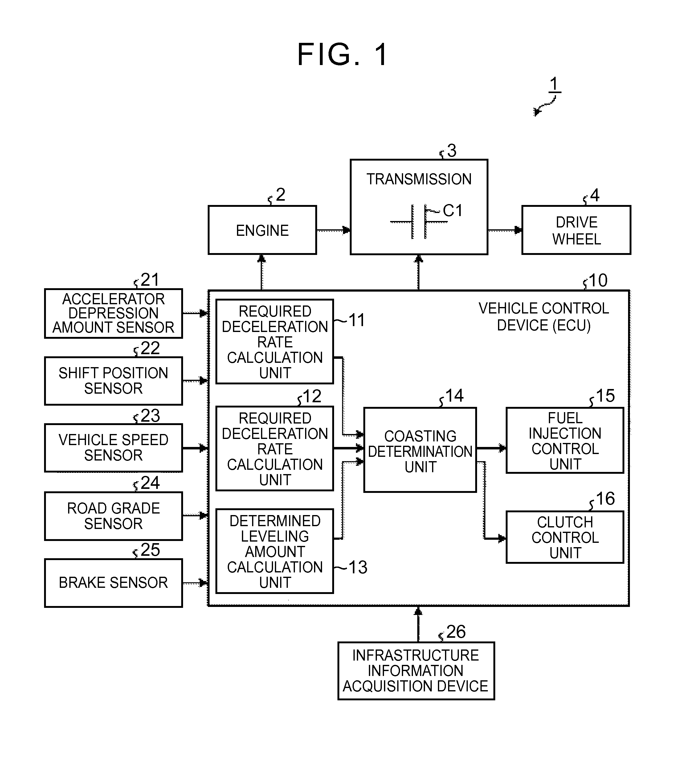
[0019]The configuration of a vehicle control device 10 according to an embodiment of the invention is initially explained with reference to FIG. 1. As shown in FIG. 1, the vehicle control device 10 of the present embodiment is installed on a vehicle 1.

[0020]The vehicle 1 is provided with an engine 2, a transmission 3, and drive wheels 4. The engine 2 is an internal combustion engine which is a drive unit of the vehicle 1. The drive power of the engine is controlled according to the fuel injection amount. The transmission 3 is a drive power transmitting mechanism that transmits the drive power generated by the engine 2 to the drive wheel 4 side. A clutch C1 that is detachably connected to the rotating shaft of the e...


PUM


Abstract

A vehicle control device is a vehicle control device for a vehicle capable of coasting, in which when there is no acceleration or deceleration request to the vehicle while traveling, power transmission between an engine and drive wheels is cut off and the vehicle is allowed to travel by inertia, wherein in a state in which there is no acceleration or deceleration request to the vehicle while traveling and power is transmitted between the engine and the drive wheels, whether or not to implement the coasting is determined by comparing a required deceleration rate Dt which is estimated as a deceleration rate to be later required of the vehicle and a coasting deceleration rate Dn which is estimated as a deceleration rate during the coasting. Where it is determined to implement the coasting, power transmission between the engine and the drive wheels is cut off and the coasting is implemented, and where it is determined not to implement the coasting, power transmission between the engine and the drive wheels is maintained. As a result, the implementation of coasting that can provide a sense of anxiety or discomfort to the driver can be suppressed.

Description

TECHNICAL FIELD[0001]The invention relates to a vehicle control device.BACKGROUND ART[0002]A vehicle is available that is capable of coasting in which an engine and drive wheels are disconnected while traveling and the vehicle travels by inertia in order to inhibit fuel consumption. For example, Patent Document 1 discloses a technique of taking an accelerator depression amount and a clutch revolution speed as indexes and determining whether or not to execute coasting on the basis of the movement of the coordinate points of those indexes on a coasting control determination map.[0003]Patent Document 1: Japanese Patent Application Publication No. 2010-203544SUMMARY OF THE INVENTION[0004]However, with the conventional technique for determining whether or not to implement coasting, such as described in Patent Document 1, the implementation of coasting can be contrary to the driver's intention to decelerate depending on the traveling environment or traveling scene of the vehicle, which ma...

Claims


Application Information

Patent Timeline
Patent Type & Authority Applications(United States)
IPC IPC(8): F02D7/00
CPCB60W10/02B60W30/18072B60W2030/1809B60W2720/106F16D48/06F16D2500/3101F16D2500/3108F16D2500/3127F16D2500/3144F16D2500/31466F16D2500/5085F16D2500/7041F16D2500/70424Y02T10/60F02D7/00
Inventor KONO, KATSUMIASAHARA, NORIMIKIM, JONGGAP
Owner TOYOTA JIDOSHA KK
Why Eureka
Try Eureka