Electromechanical damper

a damper and electronic technology, applied in the direction of gearing details, gearing, transportation and packaging, etc., can solve the problems of no longer effective axial force, and achieve the effect of reducing energy loss, compact overall construction, and saving spa

Inactive Publication Date: 2014-09-11
AUDI AG
View PDF5 Cites 0 Cited by
  • Summary
  • Abstract
  • Description
  • Claims
  • Application Information

AI Technical Summary

Benefits of technology

[0010]According to another advantageous feature of the present invention, the ring gear of the first gearbox and the ring gear of the second gearbox can form jointly with the stator housing a single-piece structure, with the planet wheels of the first and second gearboxes forming input elements via which drive torques are introduced into the first and second gearboxes. In this way, the overall construction saves space as the radially outer ring gears of both gearboxes form a unitary structure.
[0011]According to another advantageous feature of the present invention, the stator housing can be integrated as a gear element in the first gearbox and as a gear element in the second gearbox. Such a configurat...

Problems solved by technology

The axial force is no longer effective since the helical t...

Method used


Image

  • Electromechanical damper
  • Electromechanical damper
  • Electromechanical damper

Examples


Embodiment Construction

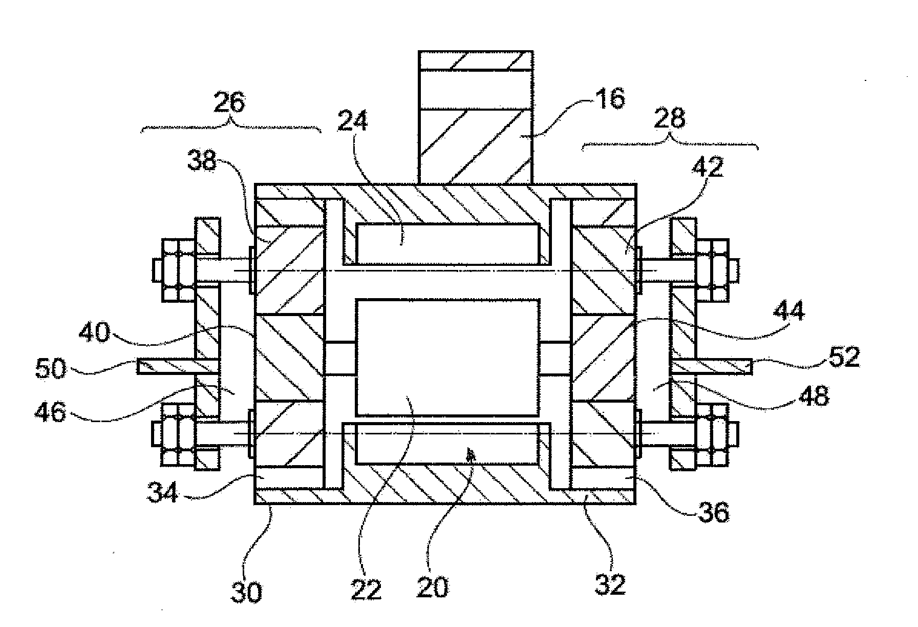
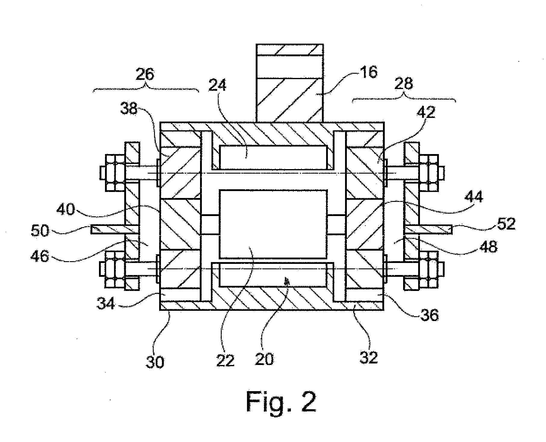
[0016]Throughout all the figures, same or corresponding elements may generally be indicated by same reference numerals. These depicted embodiments are to be understood as illustrative of the invention and not as limiting in any way. It should also be understood that the figures are not necessarily to scale and that the embodiments are sometimes illustrated by graphic symbols, phantom lines, diagrammatic representations and fragmentary views. In certain instances, details which are not necessary for an understanding of the present invention or which render other details difficult to perceive may have been omitted.

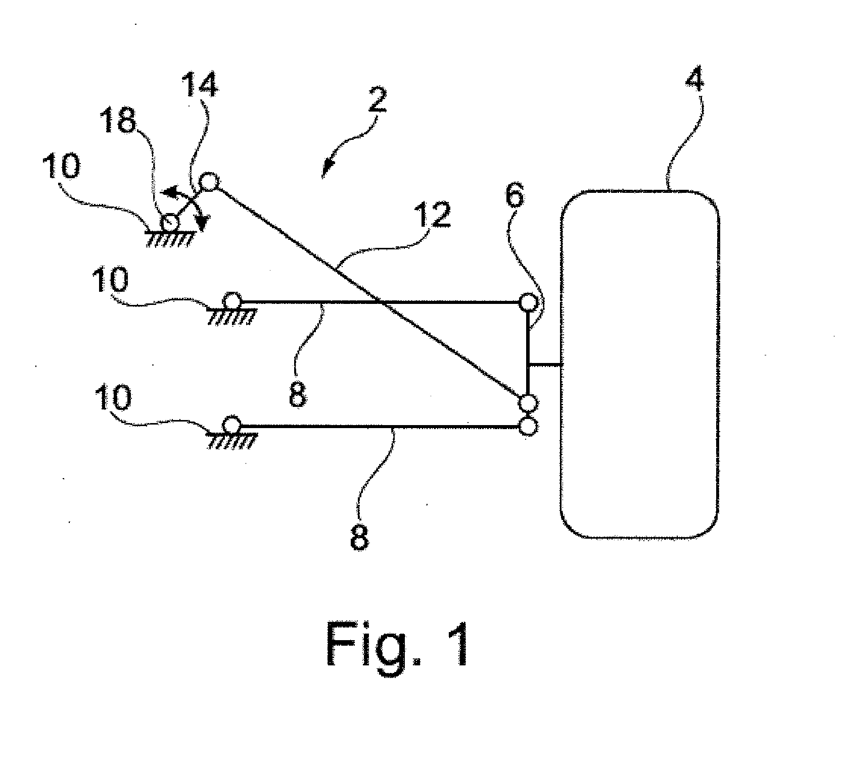
[0017]Turning now to the drawing, and in particular to FIG. 1, there is shown a schematic illustration of a wheel suspension 2 for a vehicle wheel 4 of a motor vehicle. The vehicle wheel 4 is rotatably mounted to a wheel carrier 6. The wheel carrier 6 is linked via a transverse control arm to a vehicle body 10. In addition, a semi-trailing arm 12 acts on the wheel carrier 6....


PUM


Abstract

An electromechanical damper for a vehicle for damping between two components mechanical oscillations by which a drive torque is transmittable to an electric generator for generating a damping force includes first and second gearboxes in the form of planetary gear trains, each having a sun wheel, with the sun wheels being connected to end faces of a rotor of the generator, respectively. A stator housing forms a gear element which is integrated in the first and second gearboxes. The sun wheel, ring gear and planet wheels of the first and second gearboxes are each provided with helical teeth in axial direction, with the helical teeth of the sun wheel of one of the first and second gearboxes and the sun wheel of the other one of the first and second gearboxes being directed in opposition to one another.

Description

CROSS-REFERENCES TO RELATED APPLICATIONS[0001]This application claims the priority of German Patent Application, Serial No. 10 2013 004 012.4, filed Mar. 8, 2013, pursuant to 35 U.S.C. 119(a)-(d), the disclosure of which is incorporated herein by reference in its entirety as if fully set forth herein.BACKGROUND OF THE INVENTION[0002]The present invention relates to an electromechanical damper for a motor vehicle for damping between two components mechanical oscillations by which a drive torque is transmittable to an electric generator for generating a damping force.[0003]The following discussion of related art is provided to assist the reader in understanding the advantages of the invention, and is not to be construed as an admission that this related art is prior art to this invention.[0004]An electromechanical damper may substitute a hydraulic damper in a mechanical system of a motor vehicle, where the mechanical system can oscillate. Like the hydraulic damper, the electromechanic...

Claims


Application Information

Patent Timeline
IPC IPC(8): F16H1/46
CPCF16H1/46B60G13/14F16F15/03H02K7/116B60G2204/419B60G2204/421B60G2300/60F16F15/035H02K7/1853B60G2202/22B60G2204/4191B60G7/00B60G7/04F16F15/10F16H1/28F16H1/32
Inventor WILLEMS, MARCO
Owner AUDI AG
Why Eureka
Try Eureka