Rotary mill

Active Publication Date: 2015-03-05
BIOMET UK HEALTHCARE
View PDF9 Cites 5 Cited by
  • Summary
  • Abstract
  • Description
  • Claims
  • Application Information

AI Technical Summary

Benefits of technology

[0015]The guide peg may project from a predetermined region of, and at a predetermined angle to the guide body. In this manner the region of bone to be removed may be precisely determined and fixed by the construction of the guide portion, facilitating accuracy and repeatability of milling.
[0016]The guide peg may b

Problems solved by technology

However, the design requirements for partial knee replacement prostheses are more demanding than those for total knee replacement prostheses.
Such impingement of the polyethylene bearing component onto the bone can lead to post operative pain, damage to the bea

Method used


Image

  • Rotary mill
  • Rotary mill
  • Rotary mill

Examples


Example

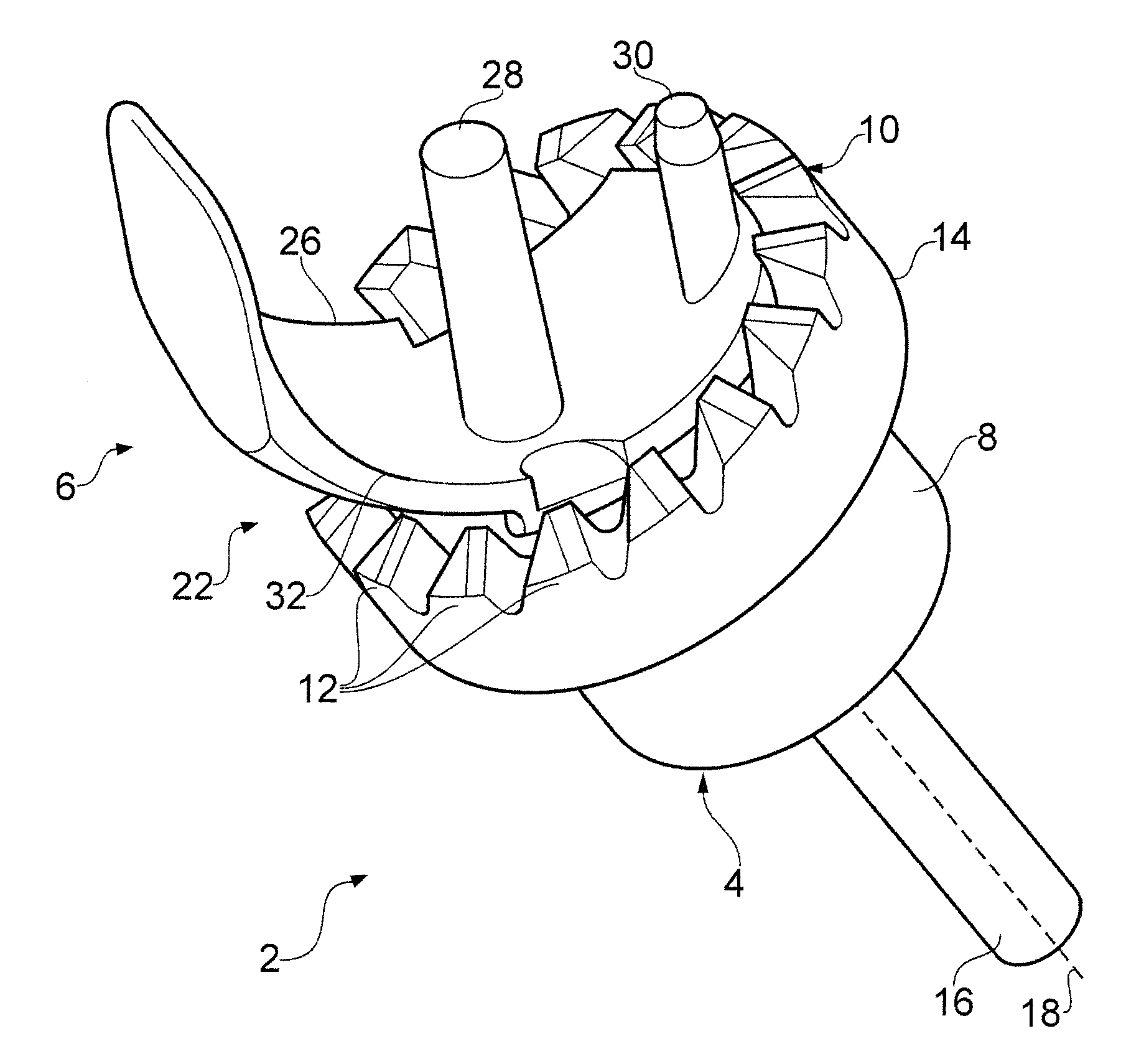
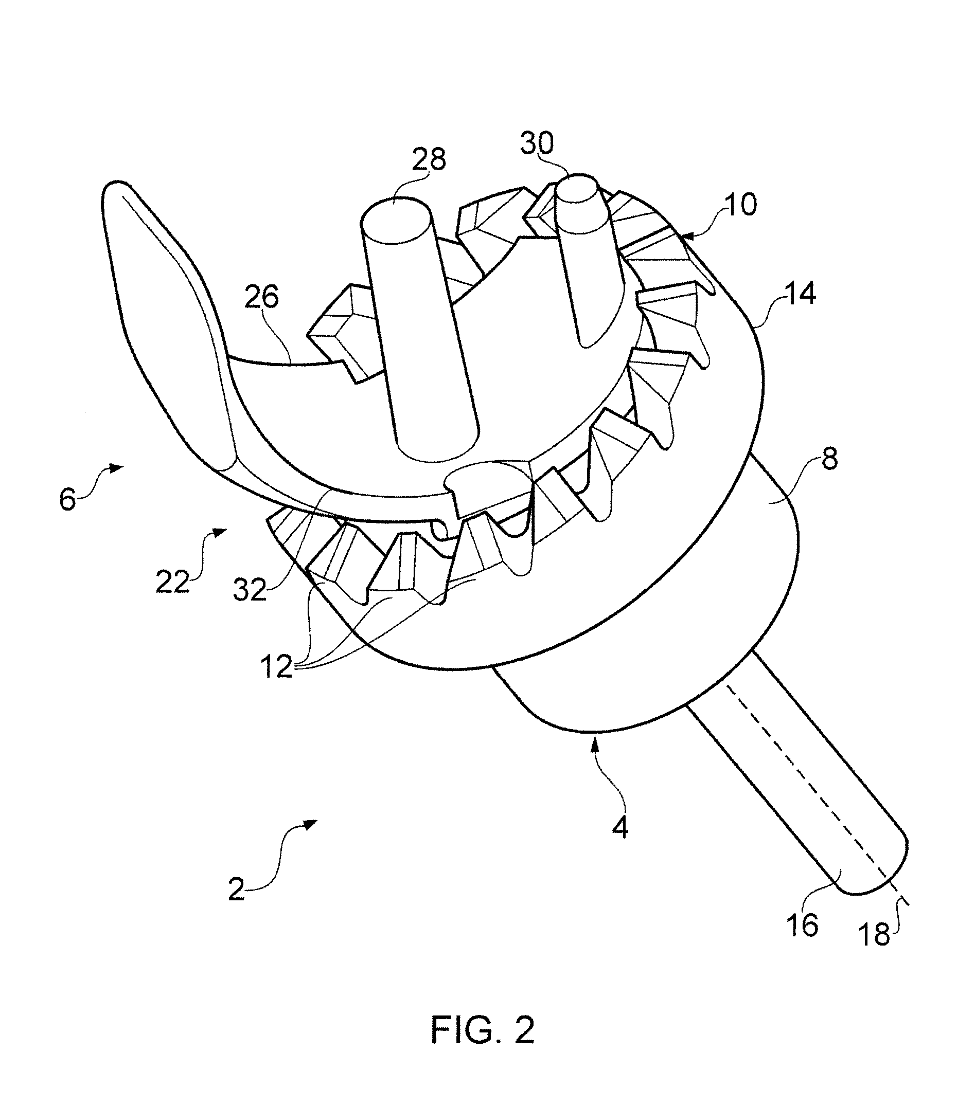
[0063]With reference to FIGS. 2 to 4, a rotary mill 2 comprises a body portion 4 and a guide portion 6. The body portion 4 comprises a rotary body 8 that terminates at one end in an annular milling surface 10. The milling surface comprises a series of milling teeth 12 that extend from the surface 10. In the illustrated embodiment, the milling surface 10 is formed on an annular shoulder 14 that protrudes outwardly from the rotary body 8. An abutment surface 15 extends radially inwardly of the projecting milling surface 10. At a second end of the rotary body 8 an integral shank 16 extends along an axis of rotation 18 of the rotary body. The shank 16 is suitable for attachment to the chuck of a surgical drill (not shown). A bore 20 extends through the rotary body 8 along the axis of rotation 18 of the rotary body 8.

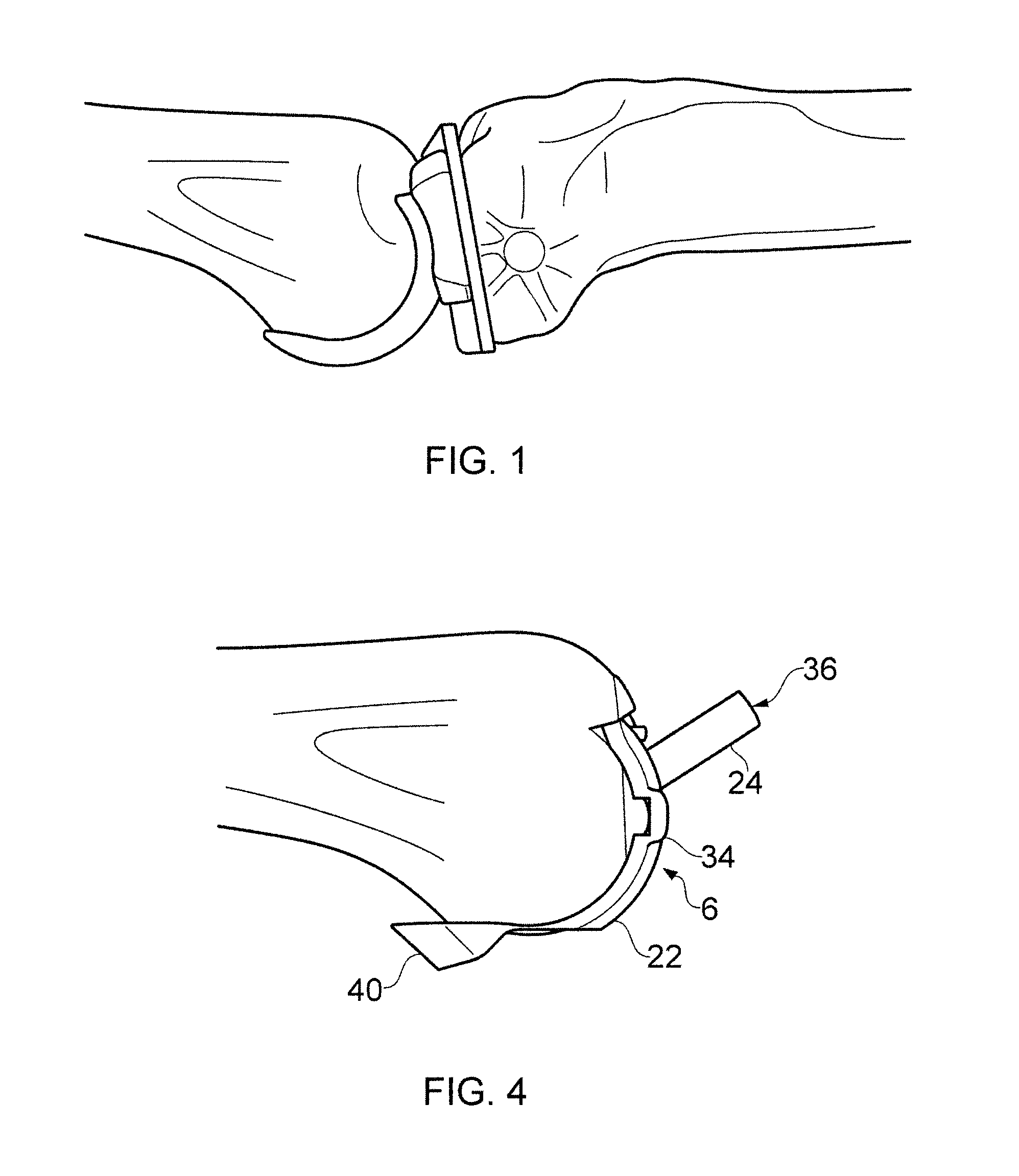
[0064]The guide portion 6 comprises a guide body 22 and a guide peg 24. The guide body 22 comprises a trail unicondylar femoral prosthesis component. The guide body thus com...


PUM


Abstract

A rotary mill is disclosed comprising a body portion (4) having a milling surface (10) and a central bore (20) extending along an axis of rotation (18) of the body portion (4); and a guide portion (6) having a guide body (22) and a guide peg (24) extending from the guide body (22), the guide peg (24) operable to be received in the central bore (20) of the body portion (4), the guide body (22) having at least one alignment feature (28, 30) which is the same as that of a prosthesis component. A method of implanting a unicondylar femoral component is also disclosed, the method comprising, a) reaming the femoral condylar surface to accept the unicondylar femoral component; b) drilling peg holes for affixing the unicondylar femoral component; c) affixing a guide portion of a rotary mill onto the prepared condylar surface using the drilled peg holes; d) reaming a portion of bone anterior to the affixed guide portion; e) removing the guide portion from the bone; and f) affixing a unicondylar femoral component to the prepared condylar surface.

Description

[0001]The present invention relates to rotary mills and similar rotary cutting devices and particularly but not exclusively relates to rotary mills for use in preparing a bone for total or partial joint replacement surgery.BACKGROUND[0002]It is known to replace all or part of a knee joint in which the joint surfaces have deteriorated, for example as a result of osteoarthritis. Such deterioration usually starts in only one of the tibeo-femoral compartments and may spread to the other at a later stage. Replacement of only one compartment of the joint can therefore be sufficient to provide prolonged relief from symptoms. Damaged bearing surfaces are replaced by a unicompartmental prosthesis which comprises a femoral implant and a tibial implant (usually metallic), which interface through a (polyethylene) bearing component disposed between the two implants.[0003]A unicompartmental or partial knee replacement (PKR) helps to conserve undamaged bone and restores more natural movement to th...

Claims


Application Information

Patent Timeline
IPC IPC(8): A61B17/16A61F2/38A61B17/17
CPCA61B17/1675A61B17/1764A61F2002/3863A61B2017/1602A61F2/3859A61B17/16A61B17/1613A61B17/1615A61B17/1617A61B17/1662A61B17/17A61B17/1739A61F2/4684
Inventor GOODFELLOW, JOHN WILLIAMMURRAY, DAVID WYCLIFFEDODD, CHRISTOPHER ALEXANDERO'CONNOR, JOHN JOSEPHALINEJAD, MONALLOYD, RUSSELLRIDLEY, DUNCAN ANDREW
Owner BIOMET UK HEALTHCARE
Why Eureka
Try Eureka