Gas measurement sensor

Active Publication Date: 2020-12-24
CSEM CENT SUISSE DELECTRONIQUE & DE MICROTECHNIQUE SA RECH & DEV
View PDF0 Cites 1 Cited by
  • Summary
  • Abstract
  • Description
  • Claims
  • Application Information

AI Technical Summary

Benefits of technology

[0016]By beam-splitting using specular reflection for splitting both portions of the incident IR light into the reference beam and the measurement beam, well-collimated beams can be produced with minimal losses, since there are no transmission or scattering losses as would be caused by e.g. using a partition wall as in the above-cited prior art, and which would also be caused when using a semi-silvered mirror, which is a common method of splitti

Problems solved by technology

However, this particular construction has several issues.
Firstly, the use of the dividing wall between the two tubes so as to split non-collimated light makes it difficult to precisely control the proportion of the IR light directed along each tube, which affects the measurement accuracy.
Furthermore, the use of waveguides on the sidewalls of the tubes is neces

Method used


Image

  • Gas measurement sensor

Examples


Embodiment Construction

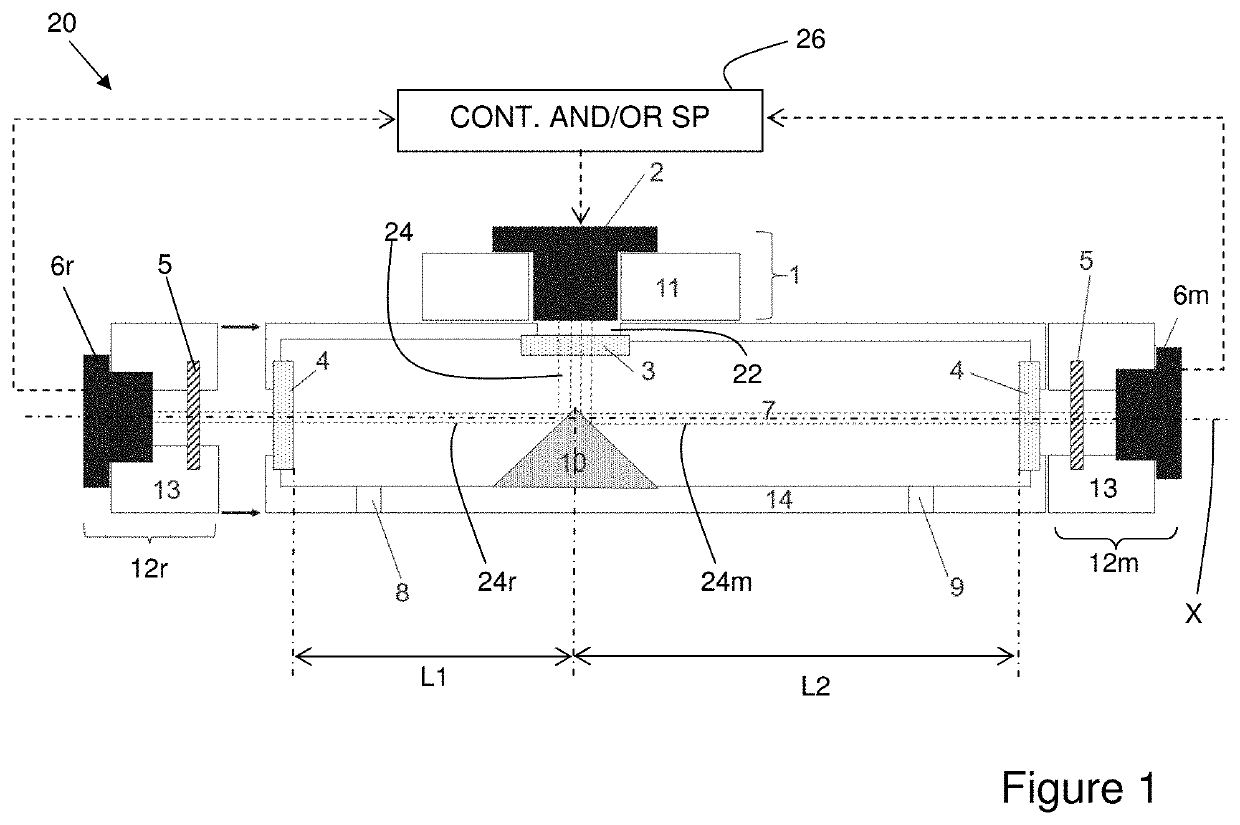
[0027]FIG. 1 illustrates schematically a gas measurement sensor 20 according to the invention.

[0028]This sensor 20 comprises a measurement chamber 7 situated inside a tube 14, which may be of cylindrical or prismatic form, and extends along a longitudinal axis X. The dimensions of the tube are not critical, and as a rough guide approximate dimensions of 70-100 mm×8-20 mm×8-20 mm would be typical. In the sidewalls of the tube 14, proximate to each of its extremities, is a corresponding gas port 8, 9, each serving either as a gas inlet or gas outlet, through which a sample can be introduced into and exhausted from the measurement chamber 7. Gas conduits can be attached to one or both ports 8, 9, a pressure differential generated between them causing the gas sample to flow through the chamber 7 as is generally known, and either or both of the ports 8, 9 may be provided with a permeating membrane (not illustrated) which may or may not be selective for the gas specie(s) of interest.

[0029...


PUM


Abstract

Gas measurement sensor including: a measurement chamber including an inlet and outlet for a gaseous sample to be measured; an infrared light source producing substantially collimated infrared light and to direct the infrared light into the measurement chamber; a beam splitter situated in the measurement chamber so as to receive the infrared light and to split the infrared light into a reference beam and a measurement beam such that the measurement beam has a longer pathway through the measurement chamber than the reference beam; a reference infrared detector arranged to receive the reference beam; and a measurement infrared detector arranged to receive the measurement beam. The beam splitter is arranged to reflect a first portion of the infrared light by specular reflection so as to form the reference beam, and to reflect a second portion of the infrared light by specular reflection so as to form the measurement beam.

Description

TECHNICAL FIELD[0001]The present invention relates to the technical field of gas measurement sensors. More particularly, it relates to an infrared gas measurement sensor exploiting absorption of infrared light by one or more gas specie(s) of interest so as to determine a concentration thereof.STATE OF THE ART[0002]U.S. Pat. Nos. 8,143,581 and 8,217,355 both disclose dual-beam non-dispersive infrared (NDIR) gas sensors, in which light from a single infrared (IR) source is directed along two parallel tubes which together form a measurement chamber. One of the tubes is longer than the other, and at the end of each is situated a corresponding IR sensor, adapted to receive infrared light. Each tube has a gas port situated near to its IR sensor, such that a gas to be tested can be made to flow through substantially the whole length of both tubes following a U-shaped path, with the result that the sample substantially fills the entire measurement chamber.[0003]In this construction, the IR ...

Claims


Application Information

Patent Timeline
IPC IPC(8): G01N21/3504G01N21/03G01N33/00
CPCG01N33/0036G01N21/0303G01N21/3504
Inventor LÜTZELSCHWAB, MARKUSTIMOTIJEVIC, BRANISLAV
Owner CSEM CENT SUISSE DELECTRONIQUE & DE MICROTECHNIQUE SA RECH & DEV
Why Eureka
Try Eureka