Color imaging element and imaging device

a technology of imaging element and element, which is applied in the field of color imaging element and imaging device, can solve the problems of poor pixel reproduction precision in a limited resolution region, low high frequency reproducibility of bayer array, and complicated demosaicing processing, so as to improve the reproduction precision of demosaicing processing, suppress aliasing, and high resolution

Inactive Publication Date: 2015-04-30
FUJIFILM CORP
View PDF48 Cites 6 Cited by
  • Summary
  • Abstract
  • Description
  • Claims
  • Application Information

AI Technical Summary

Benefits of technology

[0018]In view of the above circumstances, the present invention has been made, and an object of the present invention is to provide a color imaging element capable of reducing occurrence of false color and achieving high resolution and capable of simplifying the processing in a subsequent stage more than a conventional random array. In addition, another object of the present invention is to provide an imaging device using such a color imaging element.
[0034]The color imaging element and the imaging device of the present invention can improve reproduction precision of demosaicing processing in a high frequency region and suppress aliasing. In addition, the color imaging element and the imaging device can achieve high resolution by reducing occurrence of color moire (false color). Further, the color imaging element and the imaging device can suppress complexity in a subsequent stage.

Problems solved by technology

The color imaging element described in Japanese Patent Application Laid-Open No. 2000-308080 needs to optimize each random pattern when demosaicing processing is performed in a subsequent stage since a color filter array is random, thus causing a problem of complicating the demosaicing processing.
In addition, the color imaging element described in Japanese Patent Application Laid-Open No. 2005-136766 has a problem of poor pixel reproduction precision in a limited resolution region (particularly in the diagonal directions), because G pixels (brightness pixels) are placed in a checkered pattern.
The color imaging element described in Japanese Patent Application Laid-Open No. 11-285012 has a problem that high frequency reproducibility thereof is lower than that of the Bayer array because the ratios of the numbers of pixels of RGB are equal.
Meanwhile, the color imaging element described in Japanese Patent Application Laid-Open No. 8-23543 is not effective for a false color in a high frequency portion in a horizontal or vertical direction because the ratio of the number of pixels of G with respect to each of the numbers of pixels of R and B is six times higher than the ratio of the number of pixels of G in the Bayer array, and filter lines of only G pixels are located in the horizontal or vertical direction.

Method used


Image

  • Color imaging element and imaging device
  • Color imaging element and imaging device
  • Color imaging element and imaging device

Examples


first embodiment

[Color Filter Array ]

[0059]The color filter array 22 has the following features (1), (2), (3), (4), (5), (6), (7) and (8).

[Feature (1)]

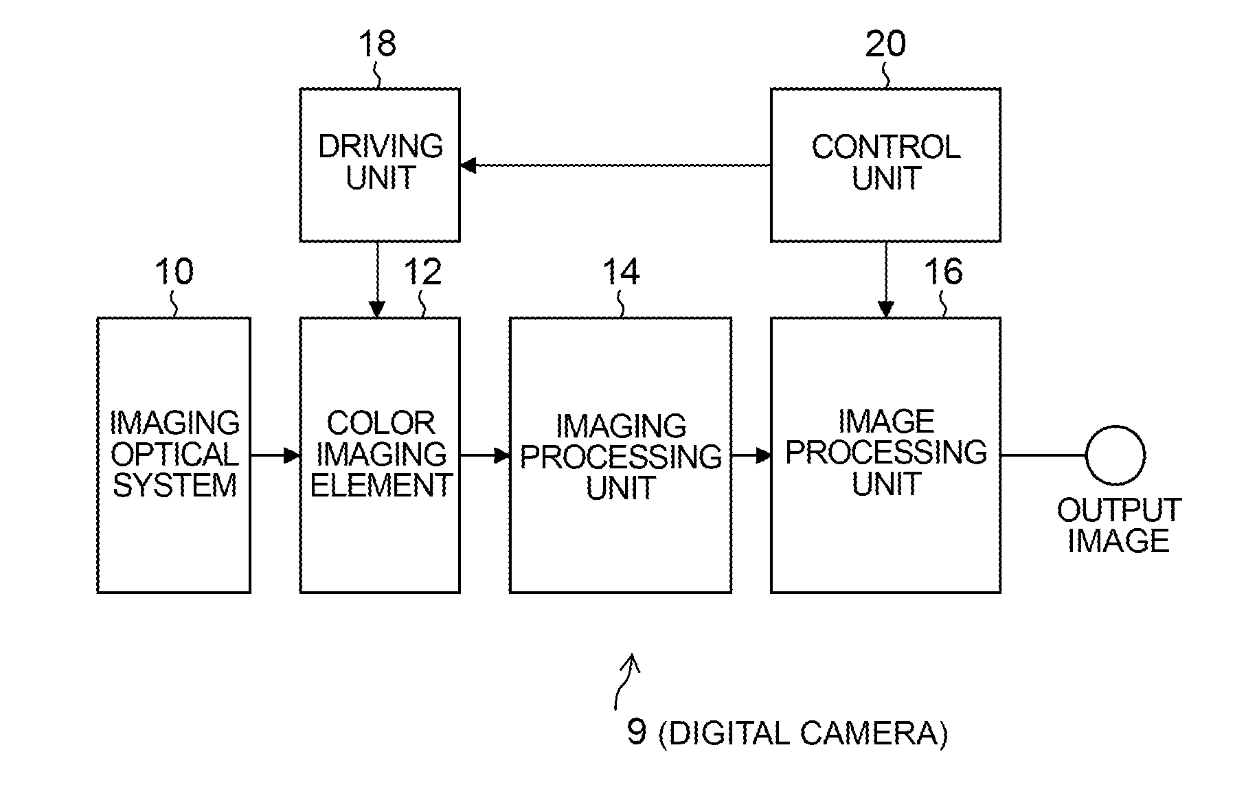
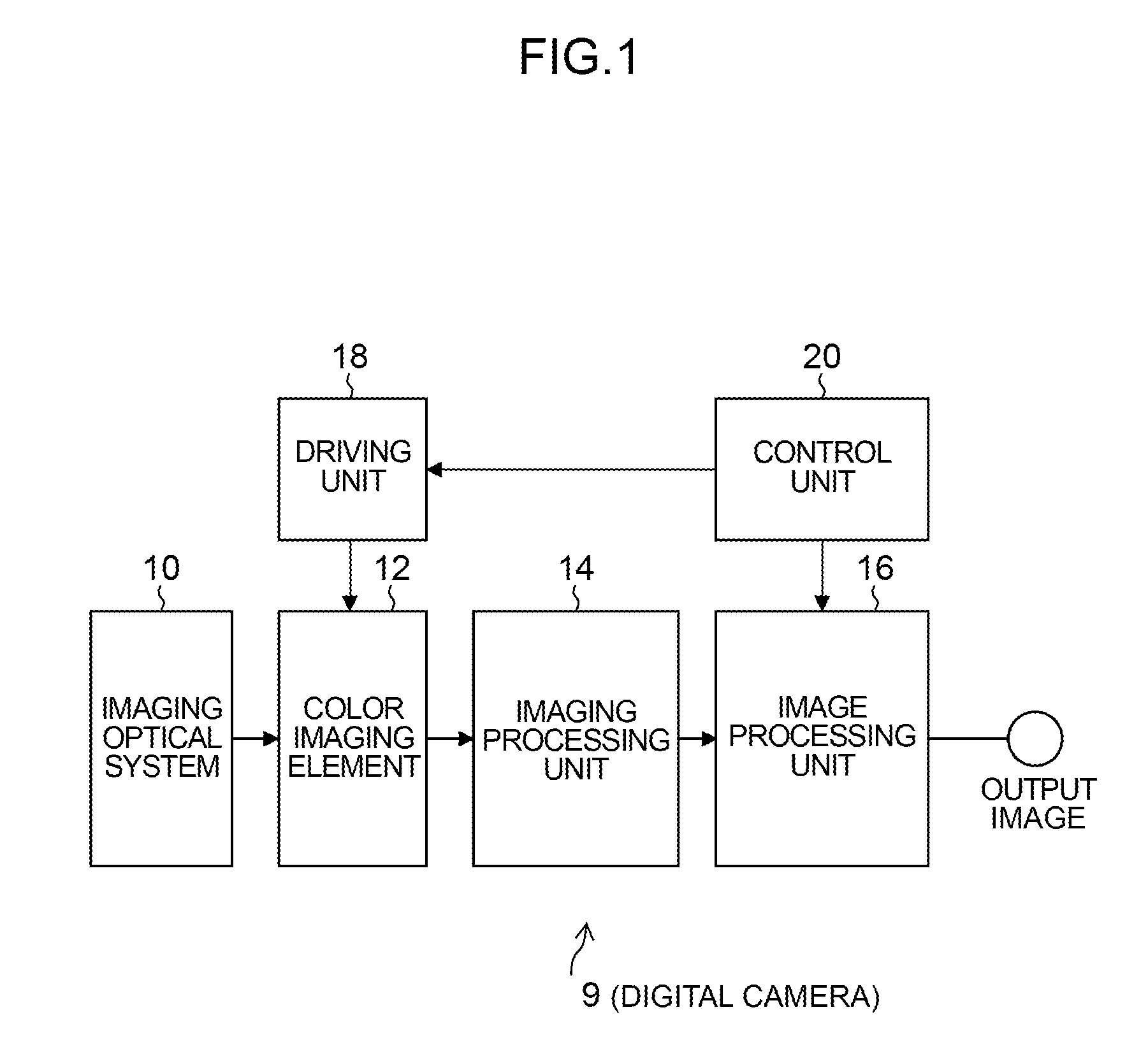
[0060]As illustrated in FIGS. 3 and 4, the color filter array 22 includes the basic array pattern P1 arranged in an array pattern corresponding to 8×6 pixels, and the basic array pattern P1 is repeatedly placed in the first direction H and in the second direction V which are orthogonal to each other. Specifically, in the color filter array 22, the R filter 23R, the G filter 23G, and the B filter 23B of each color are periodically disposed. For this reason, the R, G, and B signals read from the color imaging element 12 can be subjected to demosaicing processing and other processing according to a repeating pattern. As a result, the color filter array 22 can simplify processing in a subsequent stage more than the conventional random array.

[0061]In addition, when thinning processing is performed in units of the basic array patterns P1 to reduce an image...

second embodiment

[Color Imaging Element of Second Embodiment]

[0094]Next, with reference to FIG. 6, a color imaging element of the seventh embodiment of the present invention will be described. Note that the color imaging element of the second embodiment has basically the same configuration as the configuration of the color imaging element of the aforementioned first embodiment except for having a white pixel (also called a clear pixel) receiving white light (light in a visible light wavelength range) other than the RGB pixels. For this reason, the same reference numerals or characters are assigned to the same functions and configurations as the functions and the configurations of the above-described first embodiment, and description thereof is omitted.

[Color Filter Array of Second Embodiment]

[0095]The color imaging element of the second embodiment has a color filter array 32 different from the color filter array of the first embodiment. The color filter array 32 includes a basic array pattern P7 hav...

third embodiment

[Color Imaging Element of Third Embodiment]

[0102]Next, with reference to FIG. 8, a color imaging element of the eighth embodiment of the present invention will be described. Note that the color imaging element of the third embodiment has basically the same configuration as the configuration of the color imaging element of the aforementioned first embodiment except for having two types of G pixels. For this reason, the same reference numerals or characters are assigned to the same functions and configurations as the functions and the configurations of the above-described first embodiment, and description thereof is omitted.

[Color Filter Array of Third Embodiment]

[0103]The color imaging element of the third embodiment has a color filter array 42 different from the color filter array of the first embodiment. The color filter array 42 includes a basic array pattern P3 having R filters 23R, first G filters 23G1 and second G filters 23G2 (first filters), and B filters 23B arranged in an a...


PUM


Abstract

In the color imaging element and the imaging device according to an aspect of the present invention, a basic array pattern is repeatedly placed in a first direction and in a second direction, the basic array pattern includes four or more rectangular patterns each corresponding to 3×2 pixels each composed of a first filter, a color filter array includes therein grating filter lines surrounding the four directions of the rectangular pattern, the color filter array includes therein the first filters each disposed in each line in the first direction, in the second direction, in a third direction, and in a fourth direction, and the basic array pattern includes therein one or more second filters of each color, each disposed in each line in the first direction in the second direction.

Description

CROSS-REFERENCE TO RELATED APPLICATIONS[0001]This application is a Continuation of PCT International Application No. PCT / JP2013 / 068230 filed on Jul. 3, 2013, which claims priority under 35 U.S.C. §119(a) to Japanese Patent Application No. 2012-152676 filed on Jul. 6, 2012. Each of the above application(s) is hereby expressly incorporated by reference, in its entirety, into the present application.BACKGROUND OF THE INVENTION[0002]1. Field of the Invention[0003]The present invention relates to a color imaging element and an imaging device and, in particular, relates to a color imaging element capable of reducing occurrence of color moire and achieving high resolution, and an imaging device using such a color imaging element.[0004]2. Description of the Related Art[0005]In a single-plate color imaging element, a single color filter is provided on each pixel, and hence each pixel has color information about only a single color. For this reason, an output image of a single-plate color ima...

Claims


Application Information

Patent Timeline
Patent Type & Authority Applications(United States)
IPC IPC(8): H04N9/04
CPCH04N9/045H01L27/14625H01L27/14645H01L27/14621H04N23/843H04N25/133H04N25/135H04N23/12H04N25/134
Inventor TANAKA, SEIJIHAYASHI, KENKICHIKAWAMURA, NORIKO
Owner FUJIFILM CORP
Why Eureka
Try Eureka