Bead ring winder and setting member

a technology of bearing ring and setting member, which is applied in the direction of thin material handling, wire rings, tyres, etc., can solve problems such as complex structure, and achieve the effect of easy and accurate adjustmen

Inactive Publication Date: 2015-08-06
FUJISEIKO +1
View PDF3 Cites 0 Cited by
  • Summary
  • Abstract
  • Description
  • Claims
  • Application Information

AI Technical Summary

Benefits of technology

[0014]As described above, the present invention succeeds in easily and accurately adjusting and setting the separated distance of the separated segment from the fixed segment of the former when changing the winding diameter of a bead ring to be formed.

Problems solved by technology

This results in a complicated structure.

Method used


Image

  • Bead ring winder and setting member
  • Bead ring winder and setting member
  • Bead ring winder and setting member

Examples


first embodiment

[0023]A first embodiment of the present invention will now be described with reference to FIGS. 1 to 5(c).

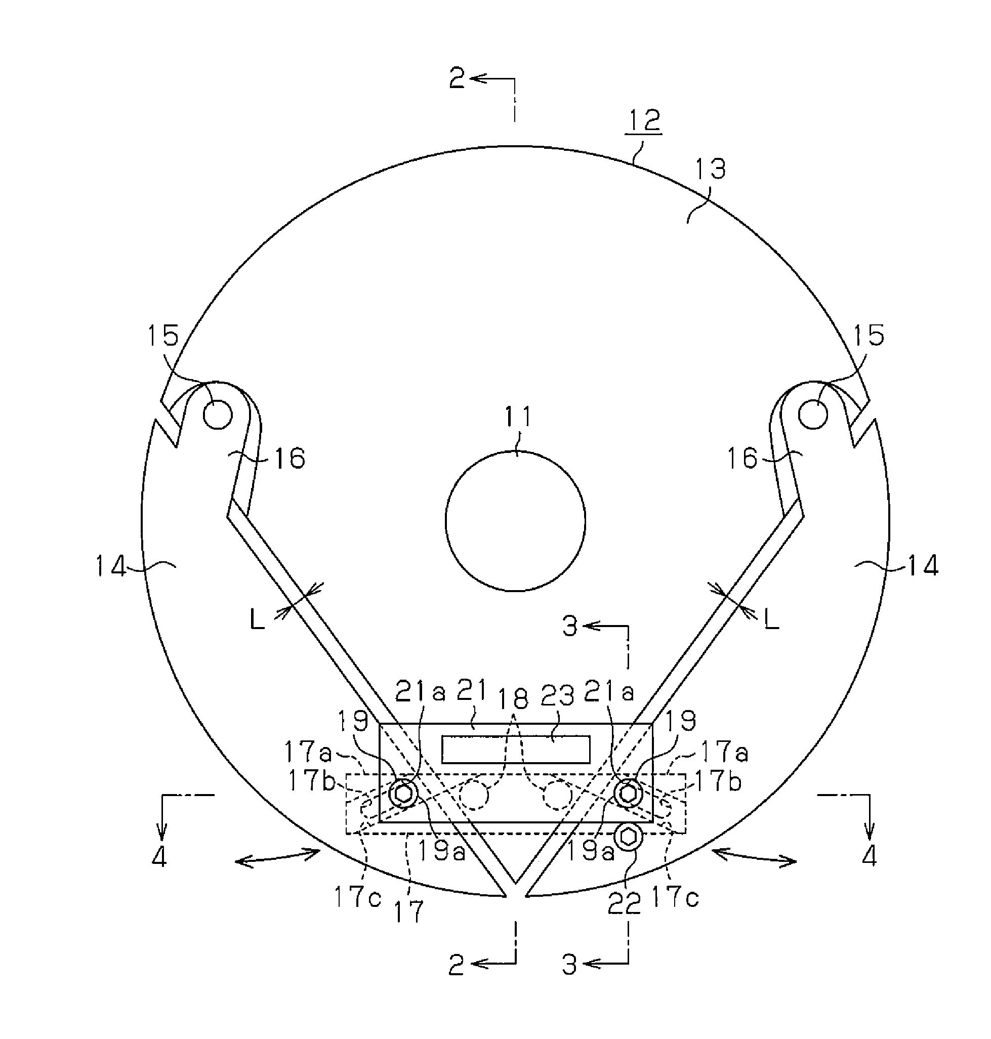
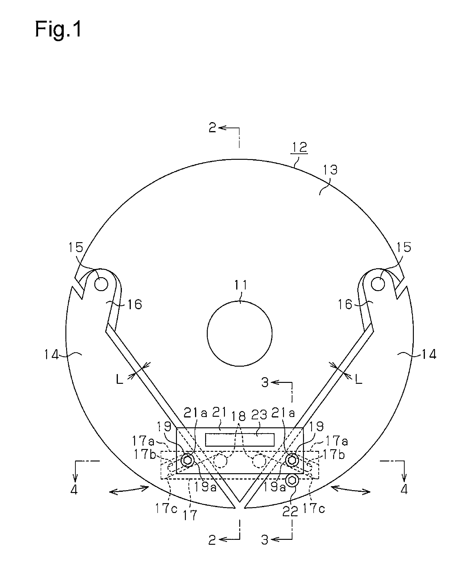
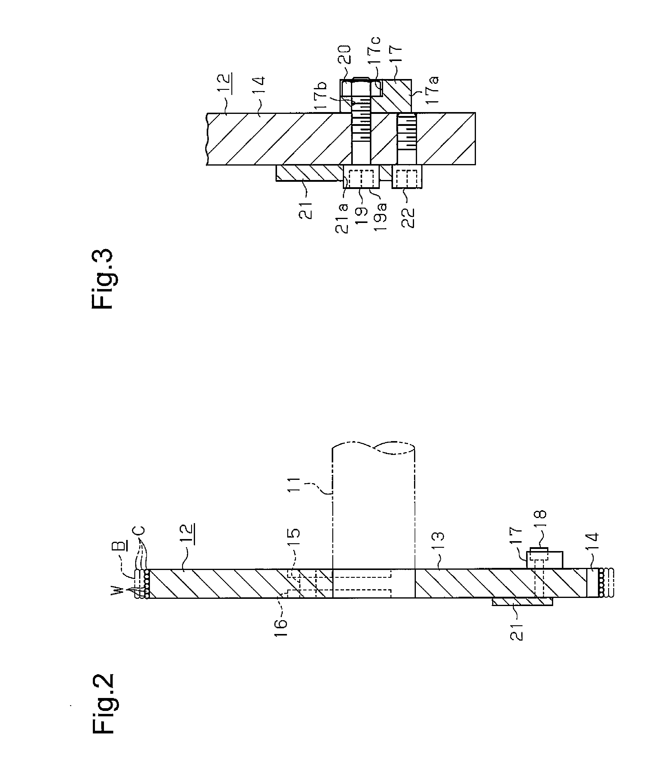
[0024]As shown in FIGS. 1 and 2, a bead ring winder includes a frame (not shown) that rotatably supports a rotation shaft 11. The rotation shaft 11 supports a former 12, which is substantially circular as a whole. The rotation of the rotation shaft 11 winds a cord C into rows around the circumference of the former 12 to form a bead ring B. The cord C is formed into the shape of a ribbon as a whole by arranging wires W in order and then insulating them with rubber.

[0025]As shown in FIGS. 1 and 2, the former 12 includes a fixed segment 13, which is fixed to the rotation shaft 11, and separated segments 14, which are coupled to the fixed segment 13 so as to be movable toward and away from the fixed segment 13. In this embodiment, two separated segments 14 are each pivotally coupled to one of opposite sides of the fixed segment 13 by a pivot shaft 15 and a coupling plate 16. The sep...

second embodiment

[0042]A second embodiment of the present invention will now be described focusing on differences from the first embodiment.

[0043]In the second embodiment, as shown in FIGS. 6 to 8(c), the fastening plate 17, which serves as a fastening member in the first embodiment, is omitted, and the setting member 21 also functions as a fastening member. Coupling bolts 24 are fastened and fixed from the front side to threaded holes in the free ends of the separated segments 14. Each coupling bolt 24 includes a head 24a that forms an engaged portion that can be engaged with a corresponding engaging portion 21a, which is formed by a hole in the setting member 21. The engaging portion 21a is engaged in a removable manner with the head 24a. This holds the setting member 21 between the separated segments 14.

[0044]An eccentric bolt 25, which serves as the fastening member, is fastened from the front side to a threaded hole in the fixed segment 13 between the coupling bolts 24. The eccentric bolt 25 in...

modified example

[0049]The above embodiments may be modified as described below.

[0050]For example, the number of the separated segments 14 may be one or three or greater. When there is only one separated segment 14, only one bolt 18 and one engaged portion 19a of the setting member 21 for the fastening bolt 19 is necessary. When there are three or more separated segments 14, a setting member 21 is arranged between the fixed segment 13 and each of the separated segments 14.


PUM


Abstract

The bead ring winder winds a cord around the circumference of a former by rotating a rotation shaft to form a bead ring. The former includes a fixed segment, which is fixed to the rotation shaft, and a separated segment, which is coupled to the fixed segment to be movable toward and away from the fixed segment, so that the former is configured to be able to increase and decrease the circumference length of the former. The bead ring winder includes a setting member, which can be replaced to set a separated distance of the separated segment from the fixed segment when changing the winding diameter of a bead ring to be formed, and a fastening plate and a fastening bolt, which fasten the separated segment to the fixed segment.

Description

RELATED APPLICATIONS[0001]The present invention is a U.S. National Stage under 35 USC 371 patent application, claiming priority to Serial No. PCT / JP2012 / 065611, filed on 19 Jun. 2012, the entirety of which is incorporated herein by reference.TECHNICAL FIELD[0002]The present invention relates to a bead ring winder that winds a cord around the circumference of a former to form a bead ring.BACKGROUND ART[0003]A conventional bead ring winder of such a type rotates a rotation shaft, which supports a former, to wind a cord around the circumference of the former and form a bead ring having a predetermined winding diameter, which corresponds to the diameter of the former.[0004]In such a structure, for example, as described in Patent Document 1, segments are arranged on a circular former to change the winding diameter of a bead ring to be formed. The segments are movable in the radial direction of the former. A bead ring having a diameter in accordance with the positions of the segments is f...

Claims


Application Information

Patent Timeline
Patent Type & Authority Applications(United States)
IPC IPC(8): B21F37/00
CPCB21F37/00B29D30/48B29D2030/487
Inventor OGUCHI, HIROSHI
Owner FUJISEIKO
Why Eureka
Try Eureka