MIMO receiving apparatus and MIMO preprocessing apparatus
What is AI technical title?
AI technical title is built by Patsnap AI team. It summarizes the technical point description of the patent document.
a preprocessing apparatus and mimo technology, applied in the field of mimo receiving apparatus, can solve the problems of increasing the complexity of signal processing, hardware requirements and network installation, and achieve the effect of efficient and flexibl
Active Publication Date: 2016-01-21
SONY CORP
View PDF1 Cites 11 Cited by
Summary
Abstract
Description
Claims
Application Information
AI Technical Summary
This helps you quickly interpret patents by identifying the three key elements:
Problems solved by technology
Method used
Benefits of technology
Benefits of technology
This patent is about a way to efficiently use MIMO transmission for terrestrial systems without the need for a second cable. The invention also includes measures to make sure that the transmission capacity of the available single cable is used efficiently, without collisions or interferences with other MIMO receive signal components of other services. This is important when several MIMO receiving apparatus are coupled over the same single cable to a single MIMO preprocessing apparatus. The patent aims to provide a more flexible and efficient solution for MIMO transmission in terrestrial systems.
Problems solved by technology
One major drawback of MIMO is the increased complexity on signal processing, hardware requirements and network installation.
Method used
Image
Click on the blue label to locate the original text in one second.
Reading with bidirectional positioning of images and text.
Examples
embodiment 1
2. The MIMO receiving apparatus as defined in embodiment 1,
further comprising a signaling extraction unit that derives said channel allocation information, in particular a signaling information containing said channel allocation information, from said multiplex signal.
embodiment 2
3. The MIMO receiving apparatus as defined in embodiment 2,
wherein said signaling extraction unit is configured to derive said channel allocation information based on a power measurement of said multiplex signal.
embodiment 3
4. The MIMO receiving apparatus as defined in embodiment 3,
wherein said signaling extraction unit is configured to derive a list of available frequency channels, indicating which frequency channels are not occupied, as channel allocation information.
5. The MIMO receiving apparatus as defined in embodiment 3,
wherein said signaling extraction unit is configured to derive a list of predetermined channel assignments, indicating to which frequency channels the MIMO receive signal components of said one or more MIMO transmission channels shall be allocated, as channel allocation information.
6. The MIMO receiving apparatus as defined in embodiment 4 or 5,
wherein said channel allocation information contains channel numbers indicating frequency channels.
7. The MIMO receiving apparatus as defined in embodiment 4 or 5,
wherein said channel allocation information contains absolute or relative frequencies indicating frequency channels.
8. The MIMO receiving apparatus as defined in any preceding em...
PUM
Abstract
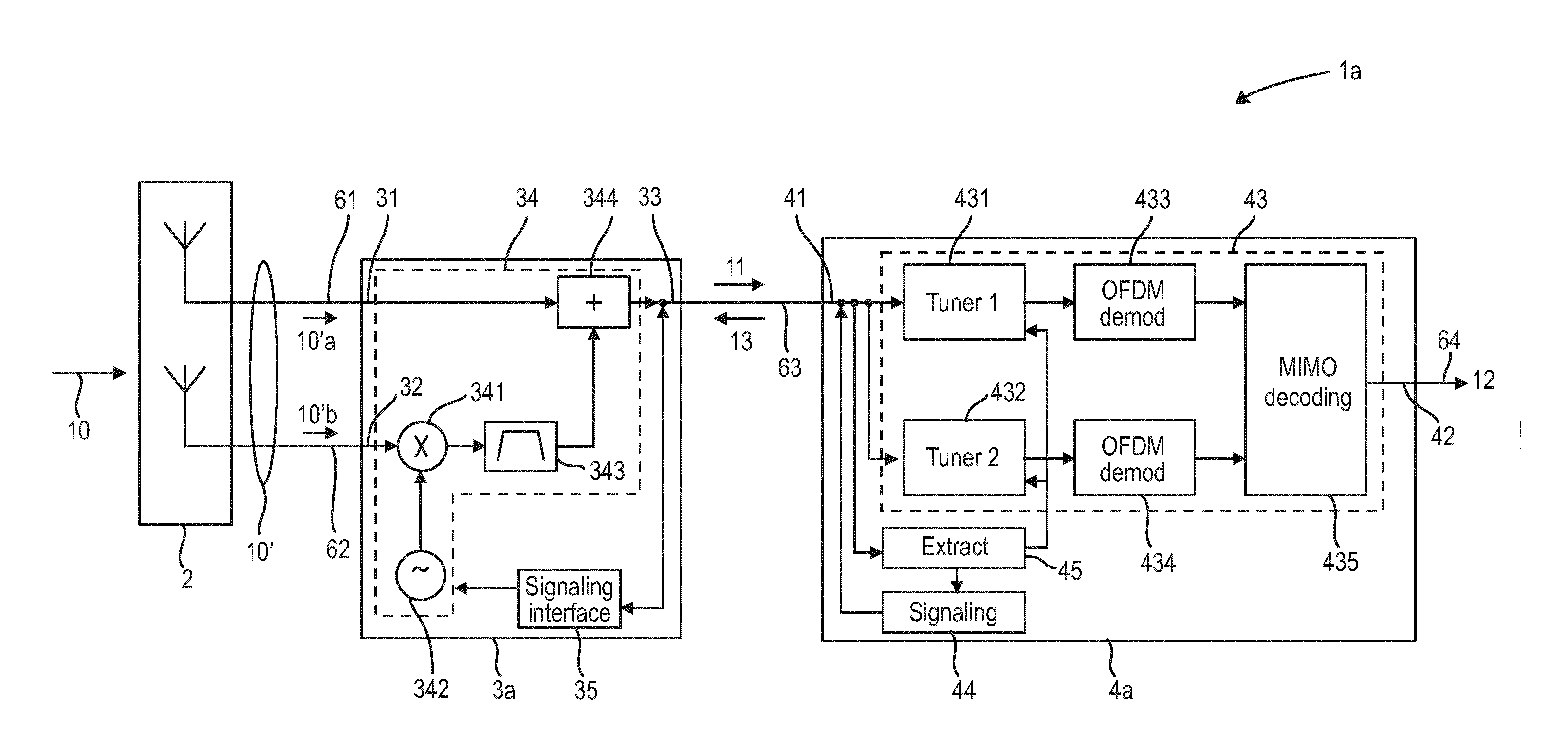
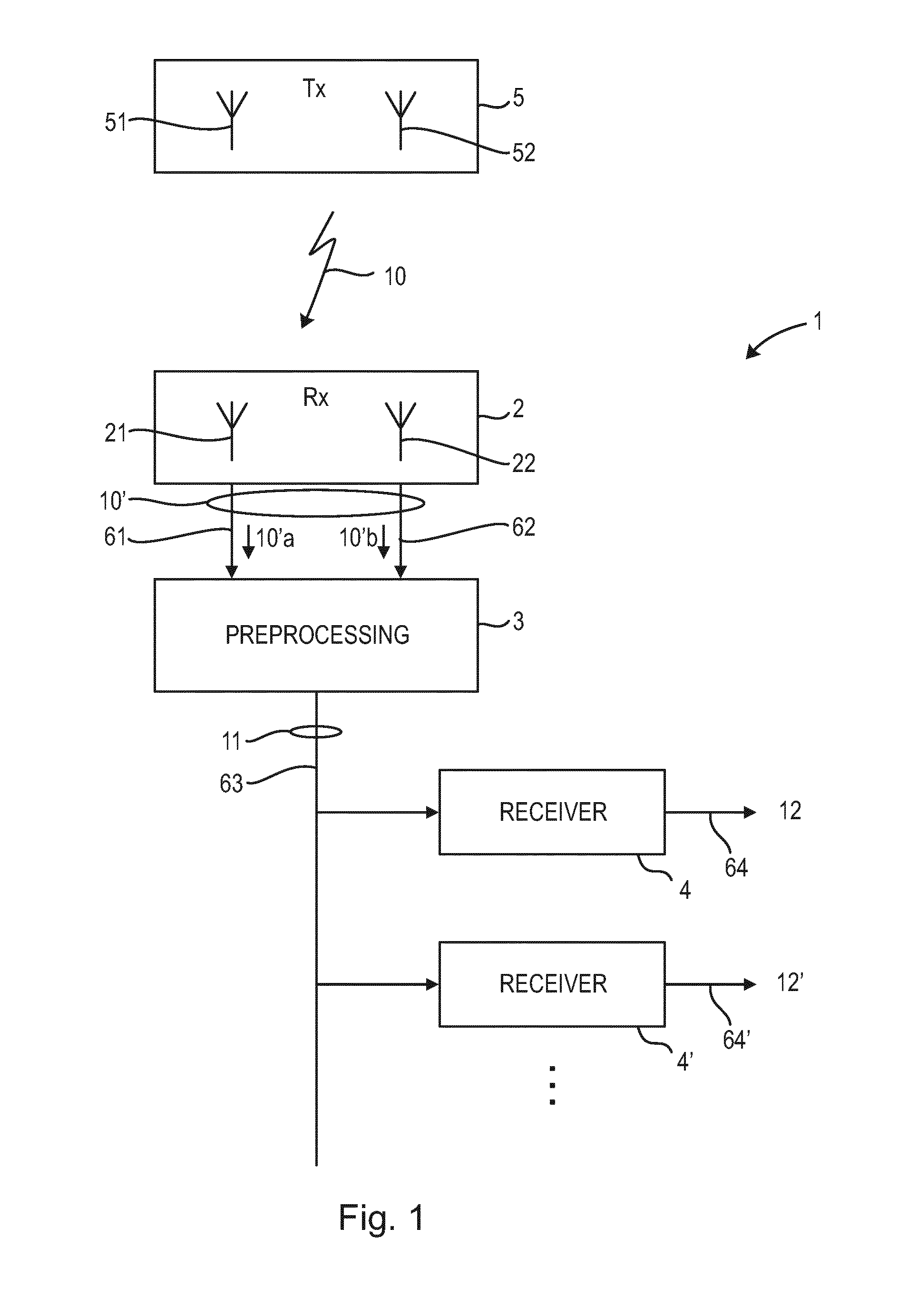
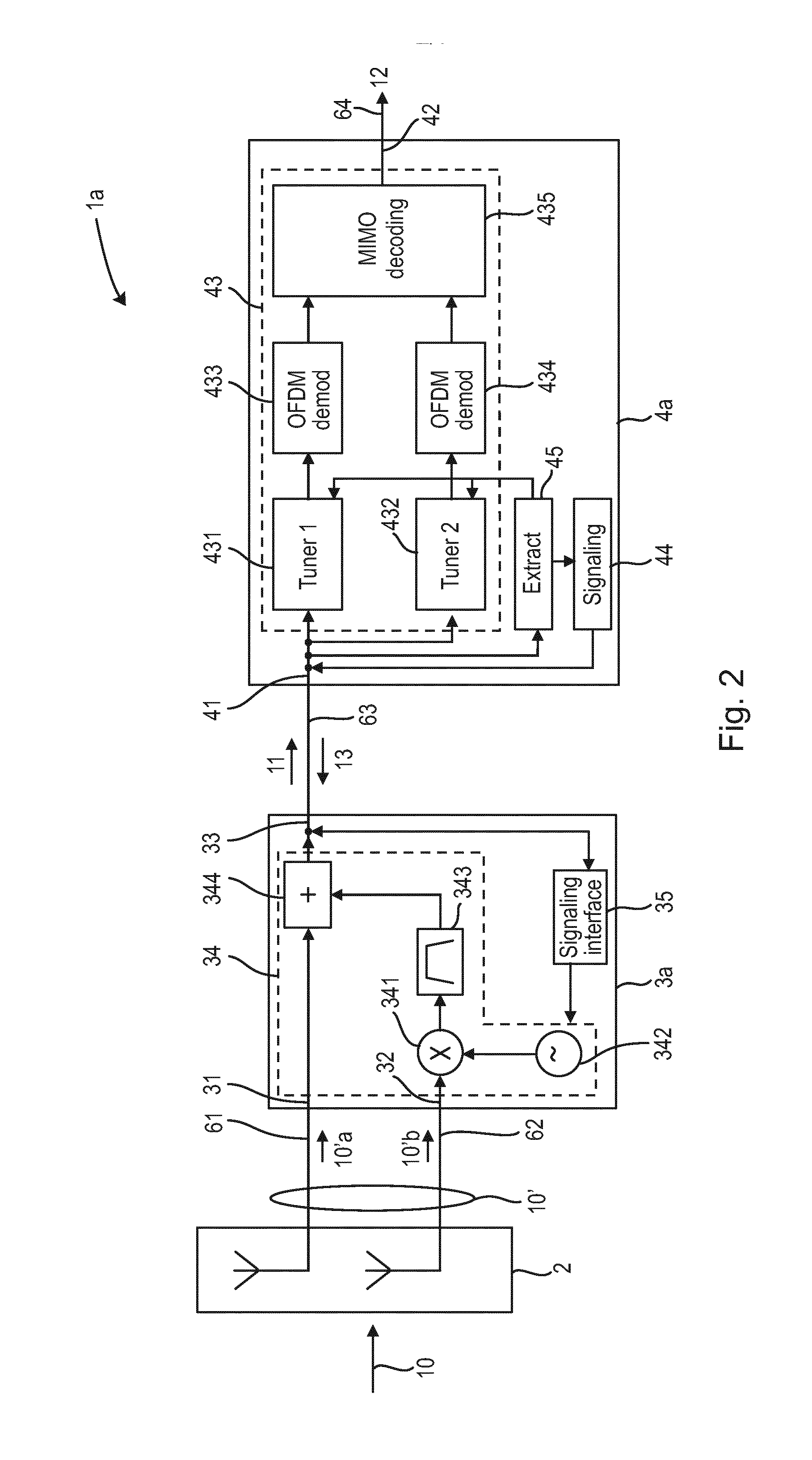
A MIMO receiving system includes a MIMO antenna apparatus that receives a MIMO transmission signal including at least two MIMO transmissionsignal streams, wherein the MIMO transmissionsignal includes one or more MIMO transmission channels and wherein a MIMO transmission channel carrying one or more services includes two MIMO receive signal components covering a same frequency channel and being included in different transmission signal streams. A MIMO preprocessing apparatus preprocesses the MIMO transmission signal and outputs a multiplex signal. One or more receiving apparatus receive the multiplex signal from the output signal path to use a service contained in the single multiplex signal and output a service data stream.
Description
BACKGROUND[0001]1. Field of the Disclosure[0002]The present disclosure relates to a MIMO receiving apparatus and a corresponding MIMO receiving method. The present disclosure relates to a MIMO preprocessing apparatus and a corresponding MIMO preprocessing method. Further, the present invention relates to a MIMO transmitting apparatus and method.[0003]2. Description of Related Art[0004]MIMO (Multiple Input Multiple Output) can be a significant measure to increase spectral efficiency for terrestrial broadcast systems. Latest standardization activities like DVB-NGH (Digital VideoBroadcasting-Next Generation Handheld) have therefore included MIMO as one element of their technical toolset. In case of DVB-NGH the receiver devices are portable or mobile, i.e. they have short stub antennas with limited antenna gain. The capacity analysis of measured MIMO channels have however shown that with increasing SNR the MIMO gain gets more significant. Therefore upcoming standardization activities l...
Claims
Application Information
Patent Timeline
Application Date:The date an application was filed.
Publication Date:The date a patent or application was officially published.
First Publication Date:The earliest publication date of a patent with the same application number.
Issue Date:Publication date of the patent grant document.
PCT Entry Date:The Entry date of PCT National Phase.
Estimated Expiry Date:The statutory expiry date of a patent right according to the Patent Law, and it is the longest term of protection that the patent right can achieve without the termination of the patent right due to other reasons(Term extension factor has been taken into account ).
Invalid Date:Actual expiry date is based on effective date or publication date of legal transaction data of invalid patent.
Patent Type & AuthorityApplications(United States)

