Connector

US20160022978A1Active Publication Date: 2016-01-28TERUMO KK

Image

  • Connector
  • Connector
  • Connector

Examples


Embodiment Construction

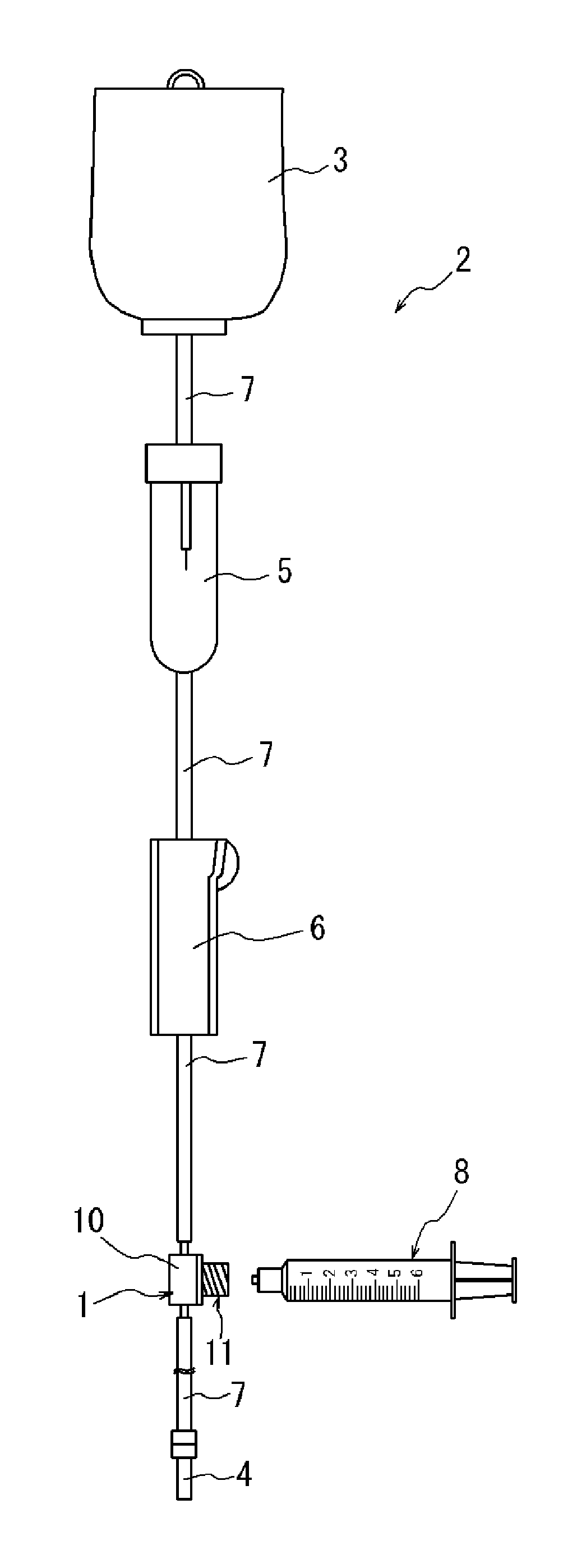
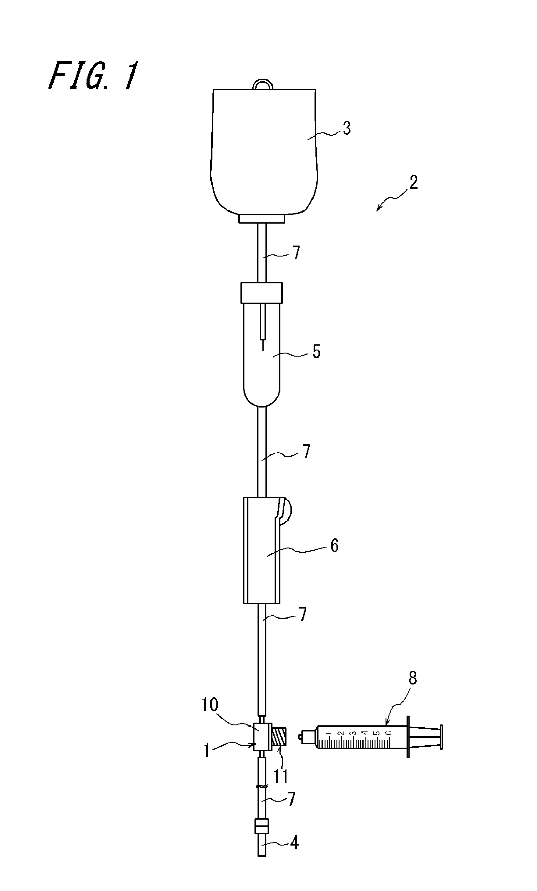
[0024]As illustrated in FIG. 1, the connector 1 which is an exemplary embodiment of the disclosure is disposed on, for example, an infusion line 2. The infusion line 2 is provided with an infusion solution bag 3 which stores liquid such as a liquid medicine, an indwelling needle 4 which is inserted into, for example, the vein of a patient, a drip infusion cylinder 5, and a clamp 6, the drip infusion cylinder 5 and the clamp 6 being disposed between the infusion solution bag 3 and the indwelling needle 4. These members are connected through a medical tube 7. The connector 1 is disposed on the infusion line 2 to enable a member to be connected such as a syringe 8 to be connected to the infusion line 2.

[0025]FIG. 1 illustrates a case in which the syringe 8 is connected to the connector 1. However, not only the syringe 8, but also, for example, another medical device such as a dialyzer, another infusion line, or an extension tube may be connected to the connector 1.

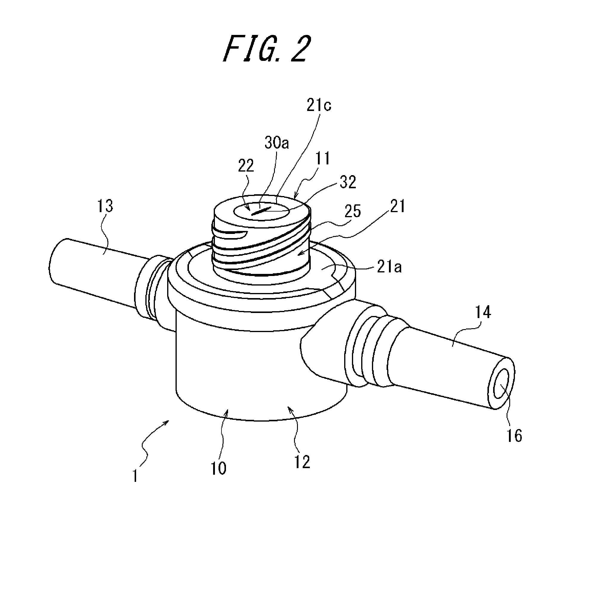
[0026]As illustrated ...


PUM


Abstract

A connector includes a connector main body having a flow path , an insertion body having a tip serving as a connection opening for the flow path , a valve body formed of an elastic body and arranged on the tip of the insertion body to block the connection opening , and a cap which holds the valve body together with the insertion body . The valve body includes a valve main body having slits , an inner projection formed in an annular shape having an outer diameter smaller than the inner diameter of the insertion body and projecting from a bottom face of the valve main body , and a pair of outer projections arranged point-symmetrically to each other with respect to the axis of the inner projection , each of the pair of outer projections projecting from the bottom face on the outer side in the radial direction with respect to the inner projection and being arranged on the inner side of the insertion body .

Description

CROSS-REFERENCE TO RELATED APPLICATION[0001]This application is a continuation of International Application No. PCT / JP2013 / 002249 filed on Apr. 1, 2013, the entire content of which is incorporated herein by reference.TECHNICAL FIELD[0002]The disclosure herein relates to a connector that is disposed on, for example, an infusion line to enable a member, such as another infusion line and various medical devices, to be connected to the infusion line.BACKGROUND ART[0003]When infusion, blood transfusion, or artificial dialysis is performed, liquid such as a liquid medicine and blood is fed into the body through an infusion line provided with a medical tube. A connector is disposed on such an infusion line, and a member, such as another infusion line and various medical devices, can be connected to the connector to join liquid such as another liquid medicine to liquid flowing inside the tube.[0004]As such a connector, there is known a connector having a structure that includes a connector ...

Claims


Application Information

Patent Timeline
28 Jan 2016
Publication
US20160022978A1
IPC
A61M39/10
CPC
A61M39/105; A61M39/286; A61M2039/2426; A61M2039/1072; A61M2039/0072; A61M2039/1083; A61M2039/1088
Inventors
UEDA, YASUHIRO