Heating control for vaporizing device

a technology of electronic vaporizer and control panel, which is applied in the direction of lighting and heating apparatus, tobacco, steam generation using steam absorption, etc., can solve the problems of charring the wick, affecting the taste of tobacco, and reducing the use effect of vaporizer,

Active Publication Date: 2016-02-25
NJOY LLC
View PDF7 Cites 67 Cited by
  • Summary
  • Abstract
  • Description
  • Claims
  • Application Information

AI Technical Summary

Benefits of technology

[0006]The present disclosure further includes a method of controlling temperature of a vaporizing device, comprising: receiving a resistance measurement of a heating element of the vaporizing device; determining a temperature of the heating element based on the resistance measurement; and adjusting an amount of power provided from a power source of the vaporizing device to the heating element based on the determined temperature of the heating element. In some embodiments, the method may further comprise supplying power from the power source to the heating element, and terminating the power before receiving the resistance measurement. For example, the power may be terminated about 10 ms or about 5 ms after supplying the power. In some embodiments, the resistance measurement may then be received from about 3 ms to about 5 ms after terminating the power. The method is repeated after a predetermined time interval, e.g., once, twice, three times, etc., for a total of n times, where n is an integer greater than 1. In some embodiments, the predetermined time interval may range from 5 ms to 1000 ms, from 10 ms to 500 ms, from 5 ms to 100 ms, such as a predetermined time interval of 10 ms, 50 ms, or 100 ms. In some em

Problems solved by technology

Nichrome and kanthal have a relatively high resistance such that passing current through them results in heating.
This type of “open loop” control with no information on the temperature of the wire can be cost effective,

Method used


Image

  • Heating control for vaporizing device
  • Heating control for vaporizing device
  • Heating control for vaporizing device

Examples


Embodiment Construction

[0012]Particular aspects of the present disclosure are described in greater detail below. The terms and definitions as used and clarified herein are intended to represent the meaning within the present disclosure. The patent literature referred to herein is hereby incorporated by reference. The terms and definitions provided herein control, if in conflict with terms and / or definitions incorporated by reference.

[0013]The singular forms “a,”“an,” and “the” include plural reference unless the context dictates otherwise. The term “about” refers to being nearly the same as a referenced number or value, and generally should be understood to encompass ±5% of a specified amount or value.

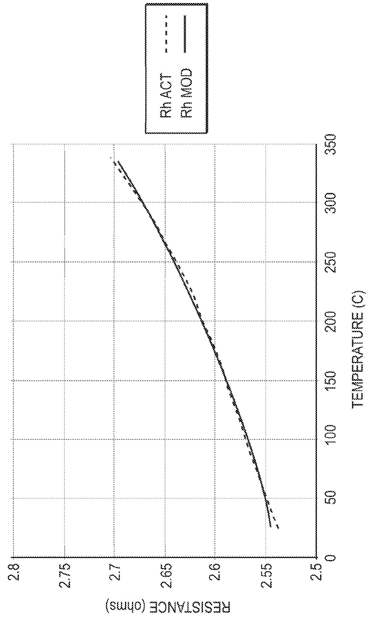
[0014]The present disclosure includes devices and methods for controlling the temperature of a vaporizing device, e.g., electronic cigarettes, electronic cigars, vaping devices, electronic pipes, electronic hookahs, and the like. By measuring the temperature or other heating or usage characteristics of the h...


PUM

PropertyMeasurementUnit
Timeaaaaaaaaaa
Timeaaaaaaaaaa
Timeaaaaaaaaaa

Abstract

The temperature of a vaporizing device, e.g., the temperature of a heating element of the vaporizing device, may be controlled according to various aspects of the present disclosure. The vaporizing device may comprise a heating element, a power source, at least one sensor in electronic communication with the heating element and the power source, and a processor configured to control the temperature of the heating element. The method of controlling the temperature may comprise receiving a resistance measurement of the heating element from the at least one sensor, determining the temperature of the heating element based on the resistance measurement, and adjusting the amount of power supplied to the heating element based on the determined temperature of the heating element.

Description

CROSS-REFERENCE TO RELATED APPLICATIONS[0001]This application claims the benefit of priority to U.S. Provisional Application No. 62 / 040,732, filed on Aug. 22, 2014, which is incorporated by reference herein in its entirety.TECHNICAL FIELD[0002]The present disclosure generally relates to electronic vaporizing devices and methods of use thereof.BACKGROUND[0003]A typical e-cigarette includes a thin nichrome or kanthal wire as a heating element. Nichrome and kanthal have a relatively high resistance such that passing current through them results in heating. The heating wires are typically controlled either by the user powering the device during an inhalation, or by sensing airflow within the device, which is the trigger for powering the heating coil. This type of “open loop” control with no information on the temperature of the wire can be cost effective, but has drawbacks. The heating wire can be over-heated, charring the wick and creating a burnt taste. Additionally, charring the wick...

Claims


Application Information

Patent Timeline
IPC IPC(8): F22B1/28A24F40/10A24F40/50H05B1/02H05B3/12
CPCF22B1/284H05B3/12H05B1/0202H05B1/0252H05B3/16H05B2203/014H05B2203/021H05B2203/022F22B1/28A24F40/10A24F40/50
Inventor QUINTANA, REYNALDO
Owner NJOY LLC
Why Eureka
Try Eureka