Double conical ivc filter

a filter and conical technology, applied in the field of medical devices, can solve the problems that current filters may not provide the desired flexibility to maintain the natural physiology of the vena cava, and achieve the effect of increasing the filtering capacity

Active Publication Date: 2016-05-12
COOK MEDICAL TECH LLC
View PDF1 Cites 1 Cited by
  • Summary
  • Abstract
  • Description
  • Claims
  • Application Information

AI Technical Summary

Benefits of technology

[0014]As one advantage of the present disclosure, the device may respond to the natural movements of the vena cava due to the slidable play between the sliders and the bars. In addition, the independent nature of the two sets of filter struts may allow the filter to respond to the forces of the vena cava, while maintaining a self-centered or self-correcting position in response to these forces. The contact portions of the device may provide stability and centering to avoid unintended tilting.
[0015]As an additional advantage, the dual conical device may provide dual or increased filtering capacity. In addition, the two sets of filter struts operate bi-directionally so that the device may be used to filter from either the proximal or distal side of the device.

Problems solved by technology

Because the vena cava is highly flexible, current filters may not provide the desired flexibility to maintain the natural physiology of the vena cava.

Method used


Image

  • Double conical ivc filter
  • Double conical ivc filter
  • Double conical ivc filter

Examples


first embodiment

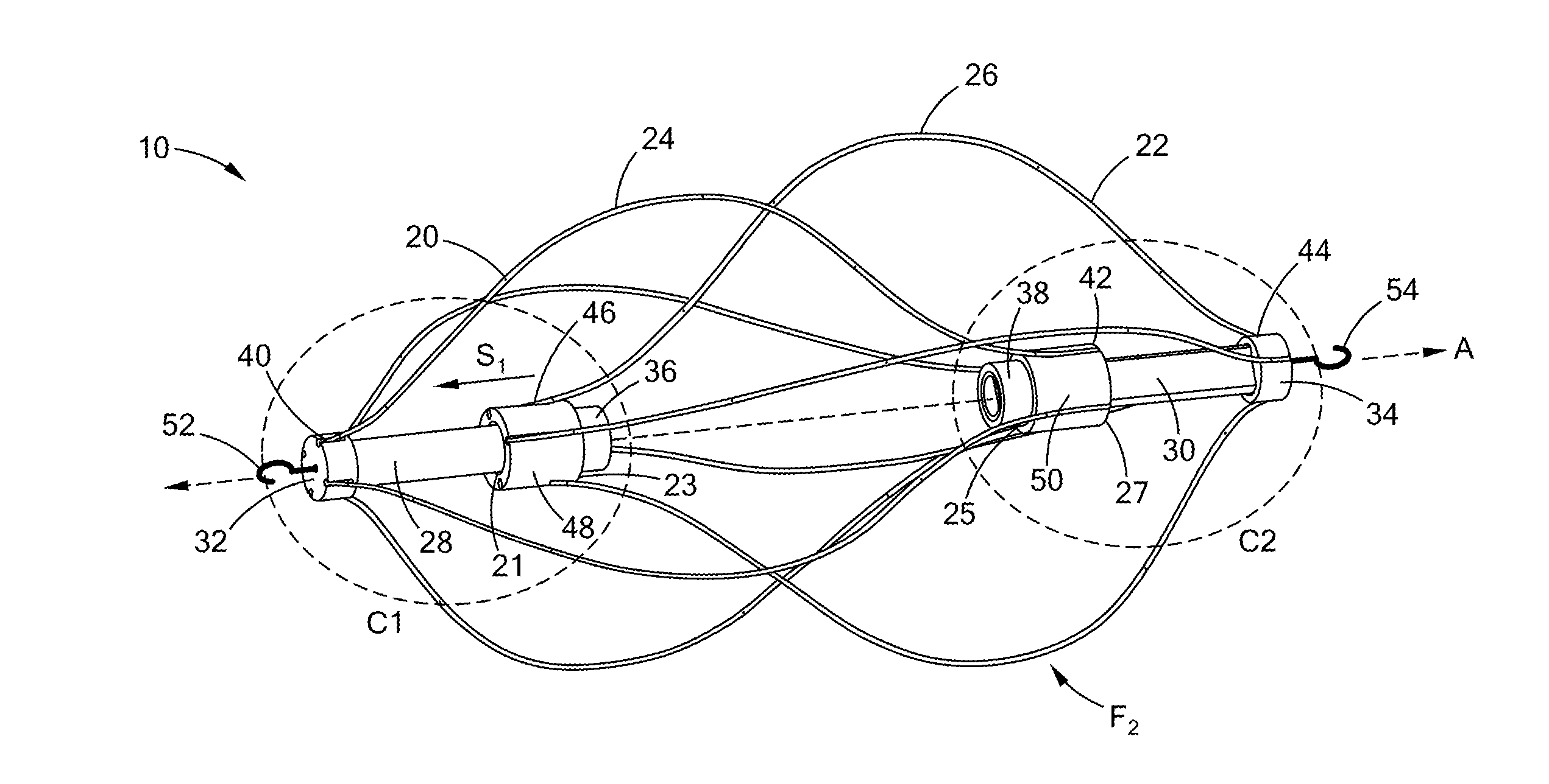
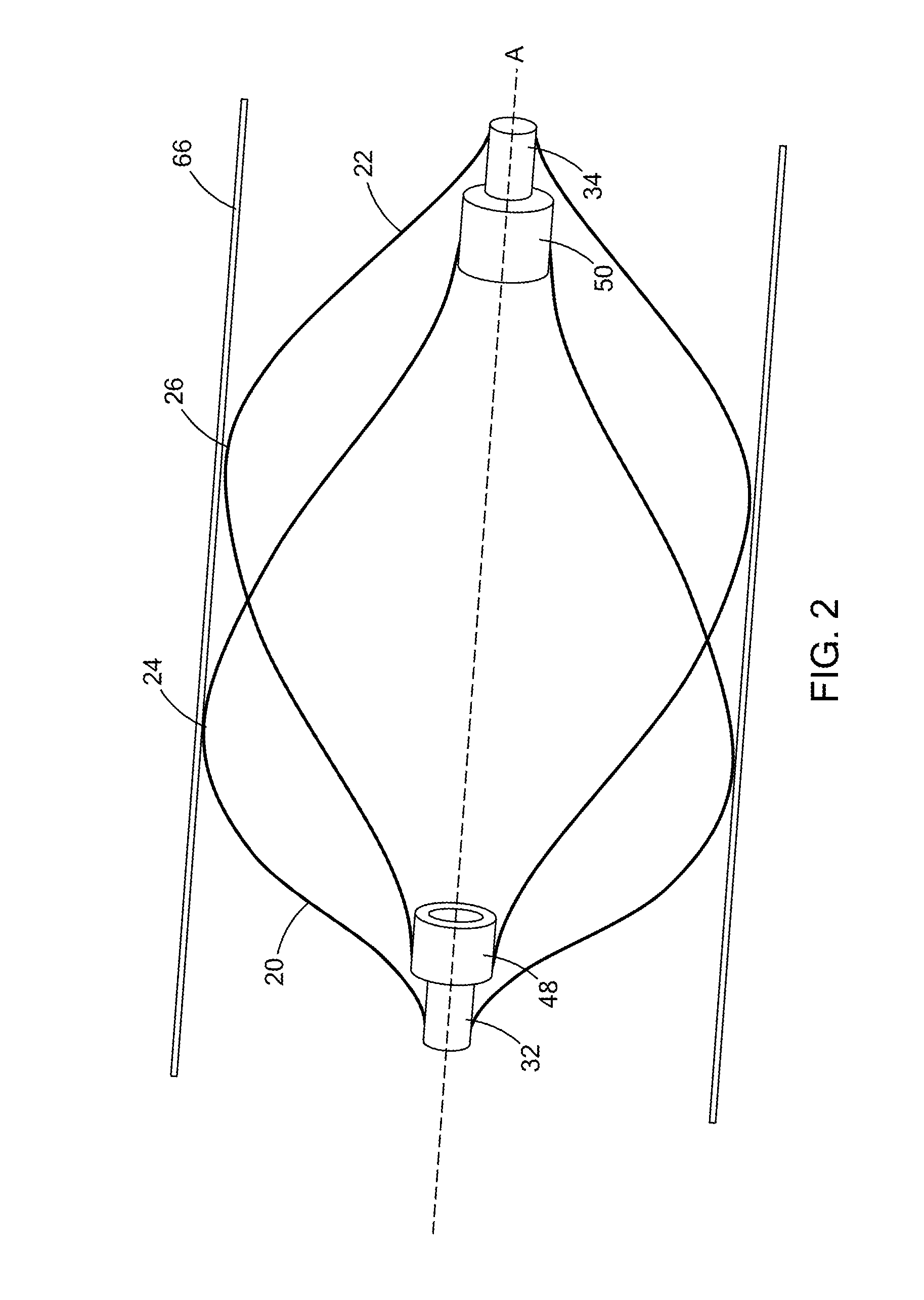
[0029]FIGS. 1A-1C illustrate the device 10. In this embodiment, the device has a first bar 28 having a first end comprising a first end cap 32 and extending distally along a first longitudinal length to a second end comprising a first center cap 36. The device further comprises a second bar having a third end comprising a second end cap 34 and extending proximally along a second longitudinal length to a fourth end comprising a second center cap 38. The first end cap 32 may be disposed proximal to the second end cap 34.

[0030]In this embodiment, the device further comprises a first slider 48 having a first slider body with a first bore formed therethrough along the longitudinal axis A of the device. The first bore defines a first opening 21 and a second 23 opening. The first bar 28 may be slidably disposed through the first and second openings (21 and 23, respectively) to allow play between the first bar 28 and the first slider 48. The second slider 50 may have a second slider body wi...

second embodiment

[0043]FIGS. 4A-4B depict the device. In this embodiment, the first and second bars further comprise first and second tracks, respectively. For example, the first bar comprises a first track 56 formed between a proximal track end 60 and the first center cap. The second bar may comprise a second track 58 formed between the second center cap and a distal track end 62. The first slider may be slidably disposed in the first track 56 and the second slider may be slidably disposed in the second track 58.

[0044]In this embodiment, the first bore is formed complementary to the first track 56 to maintain the first slider in the first track 56. In addition, the second bore may be formed complementary to the second track 58 to maintain the second slider in the second track 58. FIG. 4B shows a blown-up view of circle C3 in FIG. 4A. Here, the second track 58 is depicted with a second track length LT2 extending from the second center cap to the distal track end 62.

[0045]In addition, this embodiment...


PUM


Abstract

The disclosure provides an IVC filter device and method to filter. The device has a first bar and a first slider. The first slider has a first bore formed therethrough slidably disposed on the first bar. The device further comprises a second bar and a second slider. The second slider has a second bore formed therethrough and slidably disposed on the second bar. The device further has a first set of filter struts with a first filter strut being arcuate and attached to the first bar. The first filter strut may extend to the second slider. In addition, a second set of filter struts has a second filter strut being arcuate and attached to the second bar, extending to the first slider. When disposed in the vena cava, the device may receive a force through its filter struts and slide one of the sliders to accommodate the force.

Description

CROSS-REFERENCE TO RELATED APPLICATIONS[0001]This application is a claims benefit of U.S. Provisional Patent Application No. 62 / 076,515, filed Nov. 7, 2014, entitled “DOUBLE CONICAL IVC FILTER.” The entire contents of which are incorporated herein by reference.BACKGROUND[0002]1. Technical Field[0003]The present disclosure relates to medical devices. More particularly, the disclosure relates to a double conical vena cava filter and method of treatment with said device in the body.[0004]2. Background Information[0005]The vena cava is the largest vein in the body. This vein returns deoxygenated blood to the heart. Due to the vena cava's location, its structure is flexible as it moves with heartbeat and the diaphragm during breathing. Vena cava filters are common prophylactic devices to prevent pulmonary embolisms caused by deep vein thrombosis. Such filters can be placed using minimally invasive techniques either from the jugular or femoral vein. Such filters may operate to prevent pul...

Claims


Application Information

Patent Timeline
Patent Type & Authority Applications(United States)
IPC IPC(8): A61F2/01
CPCA61F2/01A61F2250/001A61F2002/016A61F2/0108
Inventor DELA, CHRISTIAN
Owner COOK MEDICAL TECH LLC
Why Eureka
Try Eureka