

Luminaire for emitting directional and nondirectional light
- Summary
- Abstract
- Description
- Claims
- Application Information
AI Technical Summary
Benefits of technology
Problems solved by technology
Method used
Image

Examples
Embodiment Construction
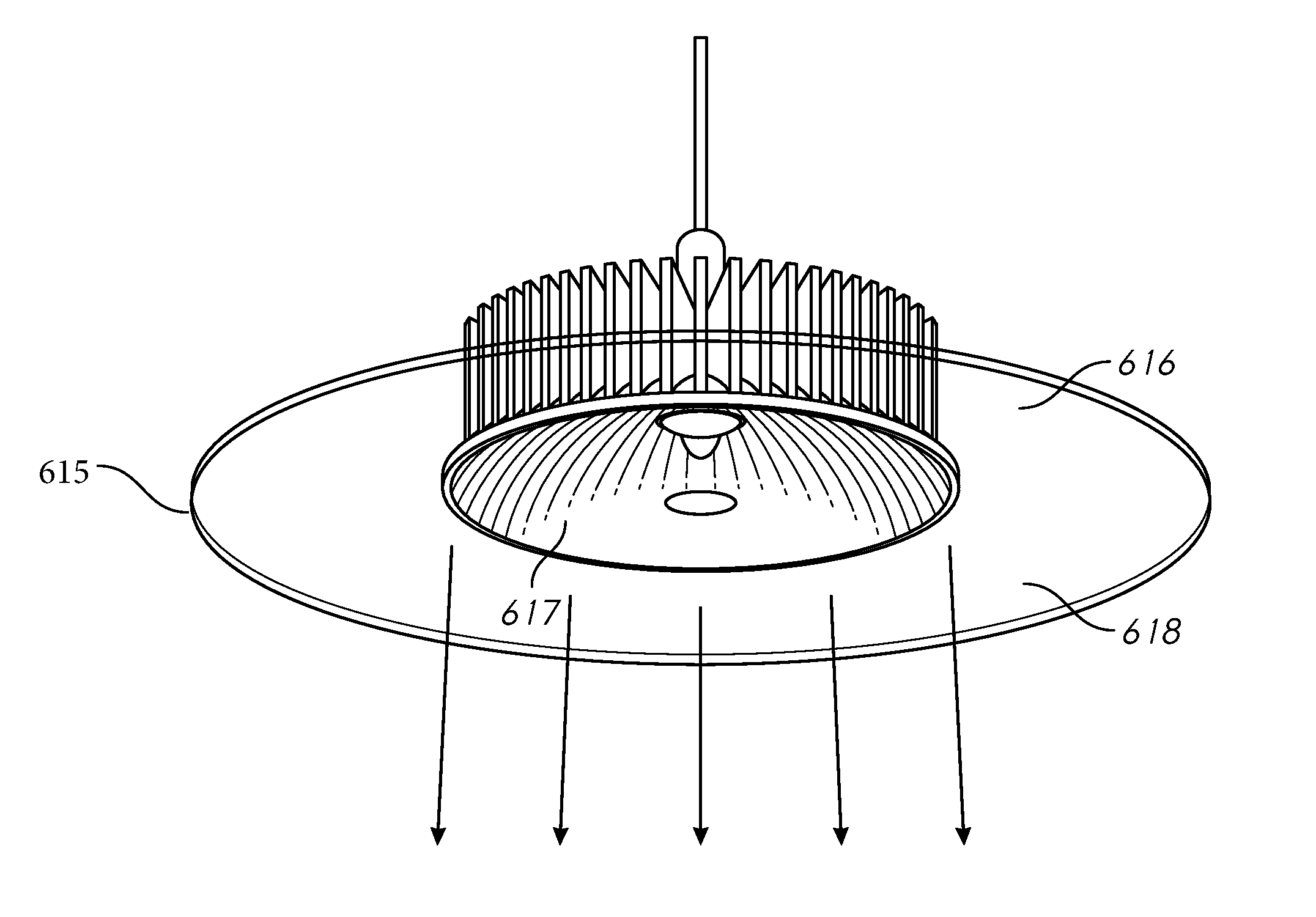
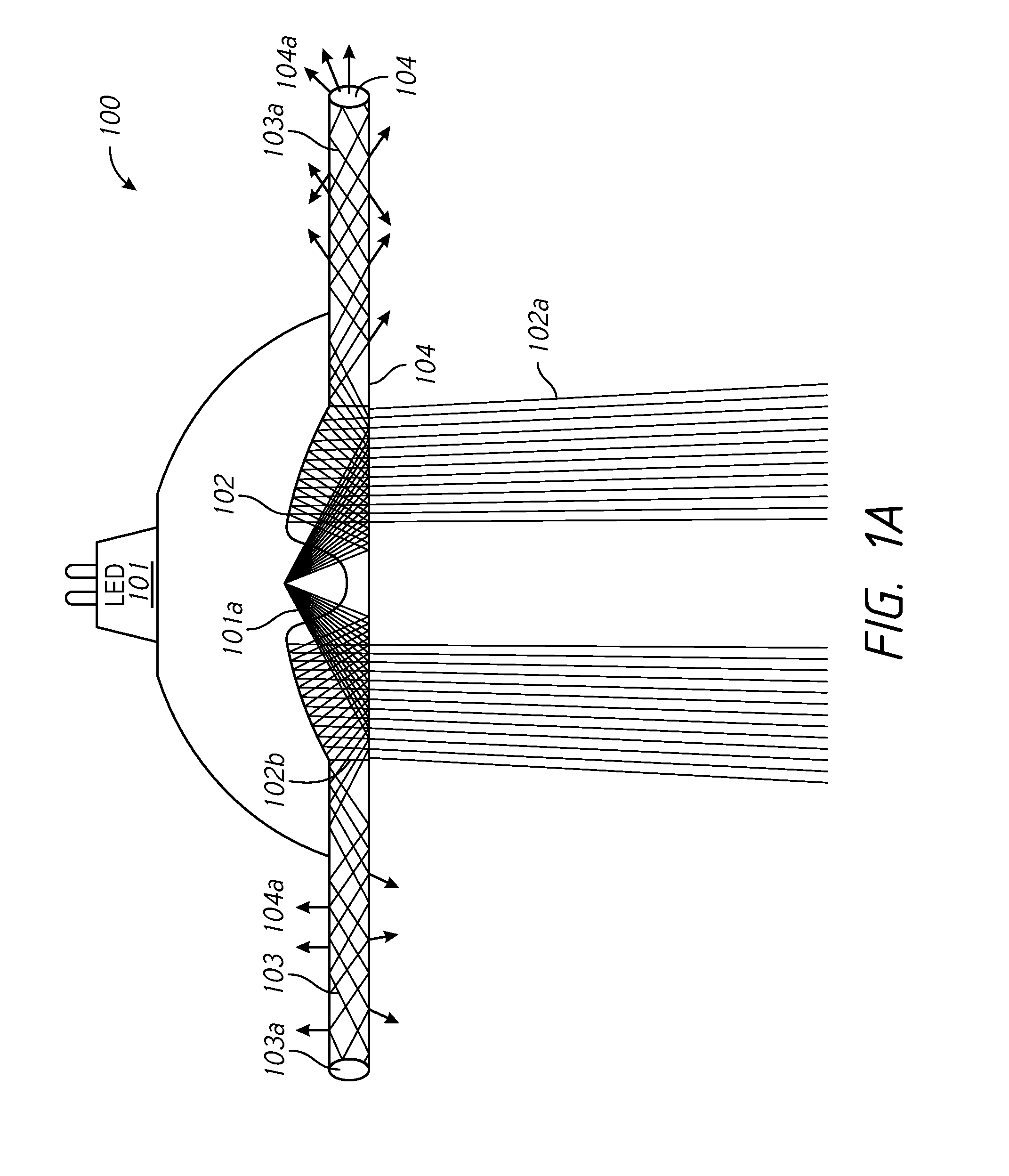
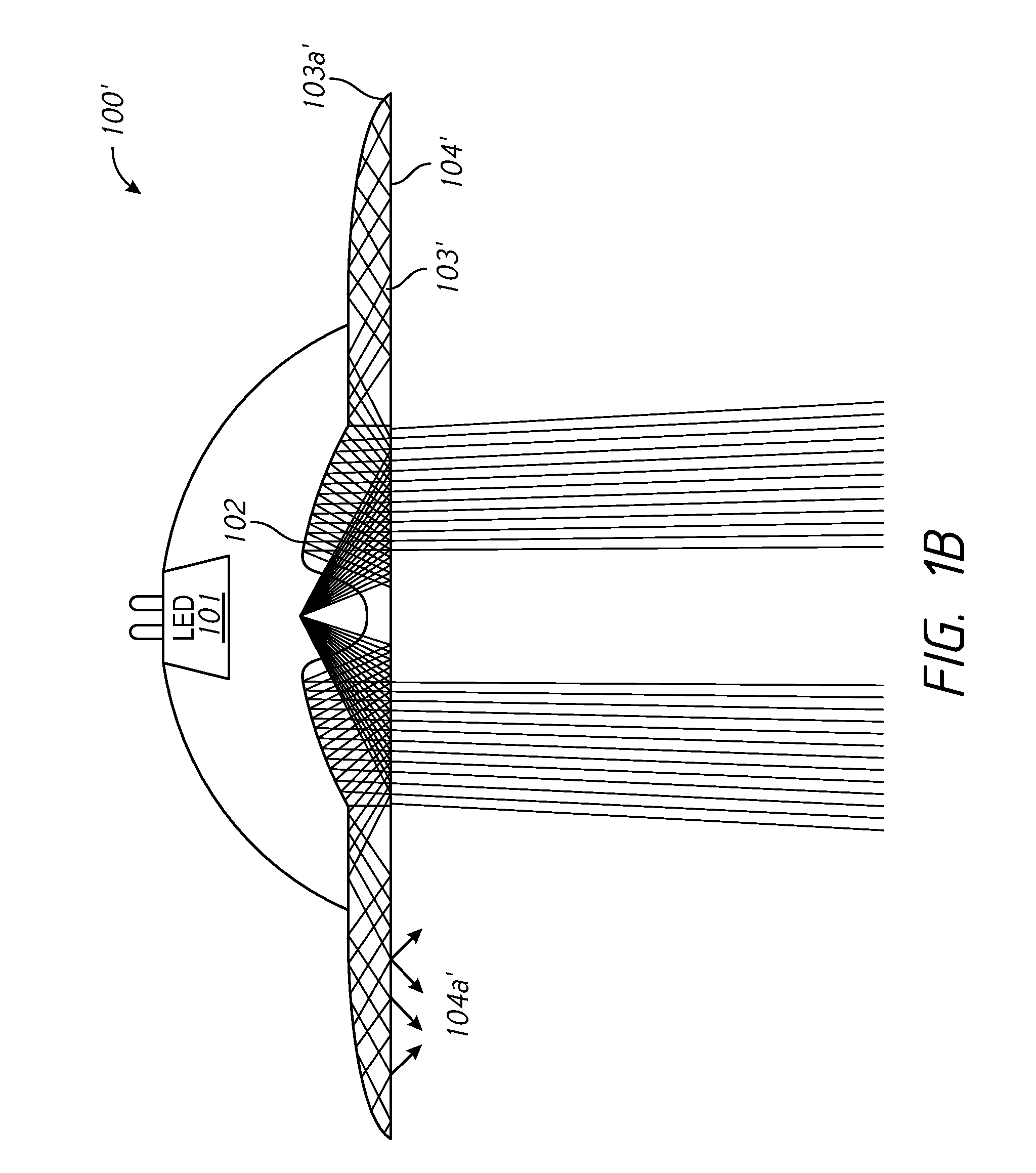
[0019]Referring to FIG. 1A, one embodiment of an light-emitting diode (LED) luminaire 100 of the present invention is shown. The luminaire 100 comprises (a) at least one LED light source 101 for emitting light rays 101a; (b) at least one directional light-emitting element 102 optically coupled to the at least one LED light source 101 to receive at least a portion of the light rays 101a and to emit directional light 102a from the luminaire; (c) at least one waveguide 103 optically coupled to the at least one LED light source 101 to receive at least a portion of the light rays 101a; and (d) at least one nondirectional light-emitting element 104 optically coupled to the at least one waveguide 103 and configured to emit non-directional light 104a. These elements and selected embodiments are described in greater detail below.
[0020]As used herein, and as understood in the art, directional light rays refers to light emission patterns having a distribution of intensity which is substantiall...
PUM
 Abstract
Description
Claims
Application Information