

Heat pump system, heat pump unit using the same, and method for controlling multiple functional modes thereof
- Summary
- Abstract
- Description
- Claims
- Application Information
AI Technical Summary
Benefits of technology
Problems solved by technology
Method used
Image

Examples
Embodiment Construction
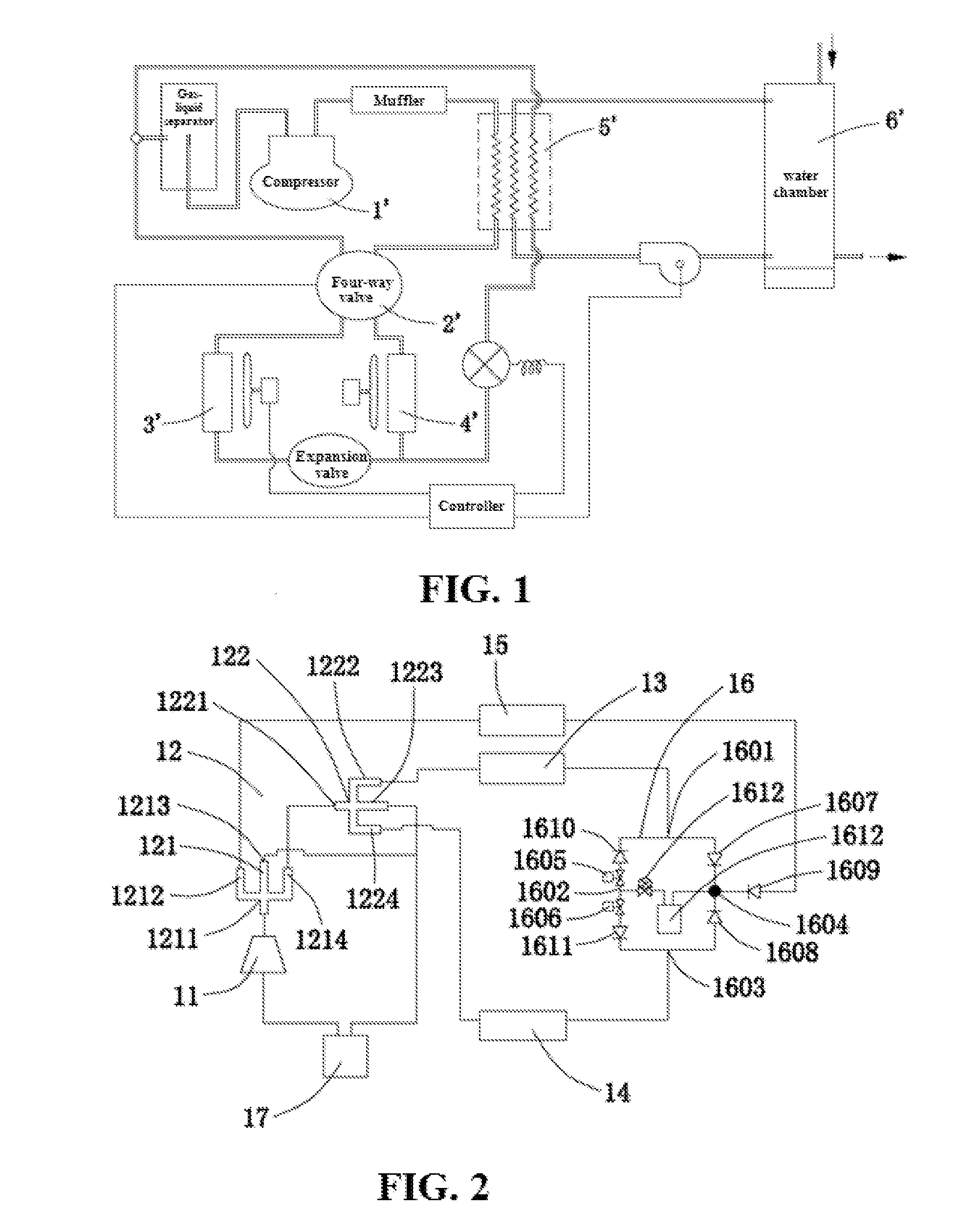
[0032]As shown in FIG. 2, according to an embodiment, the present invention provides a heat pump system 1. The heat pump system 1 includes a compressor 11, a multi-way valve 12, a first heat exchanger 13, a second heat exchanger 14, a heat-recovery-type heat exchanger 15, throttling elements 1612, and a mode-switching flow path 16.
[0033]The mode-switching flow path 16 is disposed with a first flow path, a second flow path, a third flow path, and a fourth flow path each having the throttling element 1612. Each of the flow paths can be controllably turned on or off to implement different functional modes. In a cooling mode, a cooling medium sequentially circulates through an outlet of the compressor 11, the multi-way valve 12, the first heat exchanger 13, the first flow path of the mode-switching flow path 16, the second heat exchanger 14, and the multi-way valve 12, and reaches an inlet of the compressor 11. And / or in a heating mode, the cooling medium sequentially circulates through...
PUM
 Abstract
Description
Claims
Application Information