Placement of an antenna in a wrist worn device

Active Publication Date: 2016-07-14
ARM IP
View PDF4 Cites 22 Cited by
  • Summary
  • Abstract
  • Description
  • Claims
  • Application Information

AI Technical Summary

Benefits of technology

The present invention solves the problem of limited space for an antenna in a wrist-worn device by placing the antenna on the edge of the housing, where there is no screen interference, and using a non-conductive section on the outer surface. This allows for efficient use of space and a smaller-looking device. The strap can also overlay the portion of the casing mounting the antenna without interfering with its function. The connections to the other circuitry are provided in a robust and secure manner, while the requirements of the antenna do not impact on the design of the central portion.

Problems solved by technology

Mobile devices are becoming ever smaller, and mobile devices that are worn on a wrist are necessarily limited in size.
Arranging such an antenna on a device of a constrained size that is worn by a user, such that only one face is outward looking, and that may additionally have a metal casing to protect electronic components is challenging.

Method used


Image

  • Placement of an antenna in a wrist worn device
  • Placement of an antenna in a wrist worn device
  • Placement of an antenna in a wrist worn device

Examples


Embodiment Construction

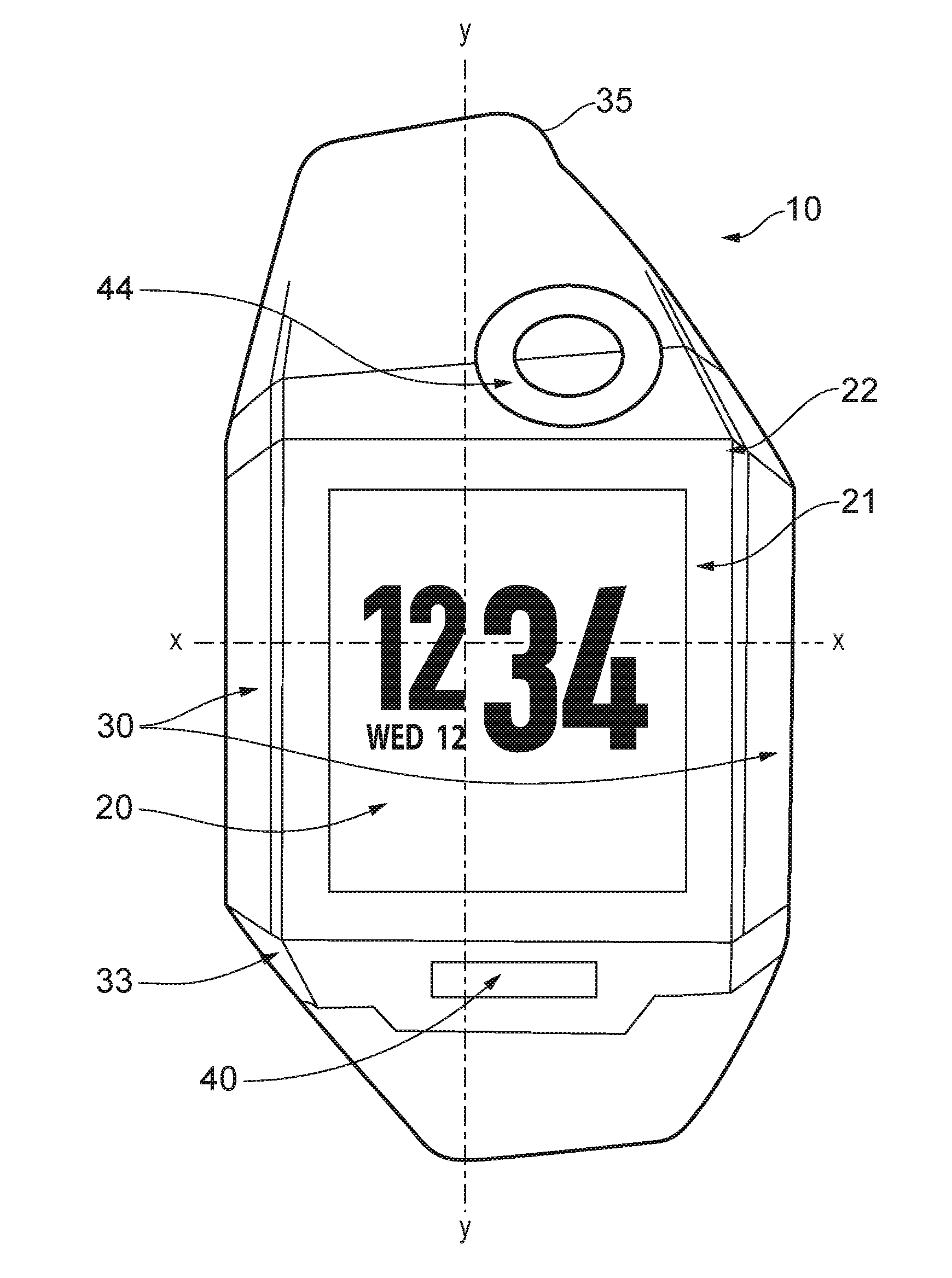
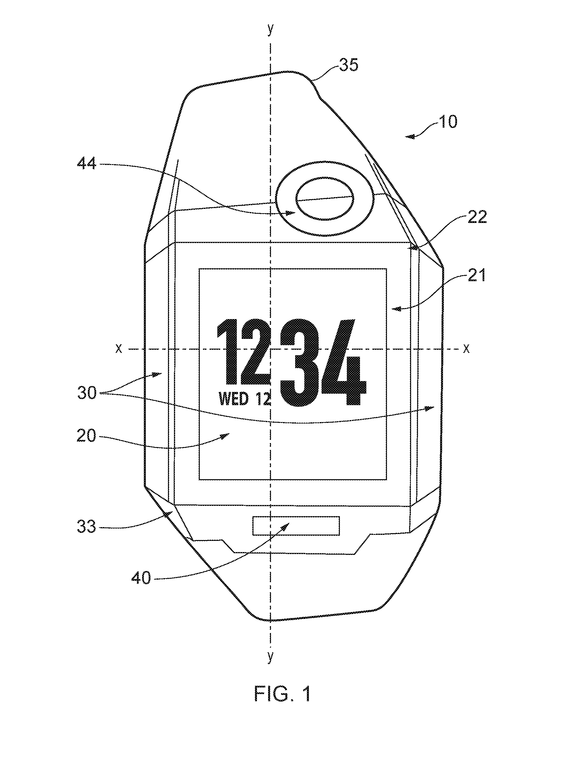
[0071]FIG. 1 shows a wrist worn device according to an embodiment of the present invention. It comprises a display screen 20 which in this Figure is displaying the time and date. The display screen can also display further information to the user.

[0072]The main section of the wrist worn device that houses the active components has a metal casing which serves as a robust mounting for the components and provides some shielding for the electronic circuits.

[0073]Much of the flat front surface 22 of the watch device is made up of the screen 20 with a framing area 21 around the display area 20.

[0074]There are inclined surfaces on either lateral side 30 on which user input devices are arranged (not shown) for a user to enter commands, such as selecting an item or zooming or scrolling through a display. There is a further user input button 33 towards the bottom left hand side of the screen which is also on an inclined angle.

[0075]The upper and lower edges to which the strap 35 is attached c...


PUM


Abstract

A wrist worn device having a main body portion and a strap portion. The main body portion comprises a housing for housing a processor, communication circuitry, a screen and tin antenna. The strap portion comprises a strap for attaching the main body portion to a wrist. The housing comprises a central portion that supports the screen and edge portions arranged around the central portion, one of the portions comprising a non-conductive section on an outer surface of said wrist worn device facing away from said wrist when worn; wherein the antenna is supported within the housing in the one of the edge portions comprising the non-conductive section, such that there is an electromagnetic wave path from the antenna to the outer surface through at least a portion of the non-conductive section wherein a portion of the strip overlays the antenna and a portion of the non-conductive section at the outer surface, the portion of the snap comprising a non-conductive portion.

Description

RELATED APPLICATIONS[0001]The present application is a National Phase entry of PCT Application No. PCT / GB2014 / 052539, filed Aug. 19, 2014, which claims priority from GB Patent Application No. 1314759.0, filed Aug. 19, 2013, said applications being hereby incorporated by reference herein in their entirety.FIELD OF THE INVENTION[0002]The present invention relates to the field of mobile devices and in particular, of wrist worn devices and the placement of antennae in such devices.BACKGROUND OF THE INVENTION[0003]Mobile devices are becoming ever smaller, and mobile devices that are worn on a wrist are necessarily limited in size. Furthermore, given their small size much of the outer surface will be covered by a screen in order to allow the screen to have an acceptable size to display information. The electronic components of such devices will generally be contained within a main body portion beneath the screen and will generally be protected by a metal casing.[0004]Traditionally wrist w...

Claims


Application Information

Patent Timeline
IPC IPC(8): H04M1/02H04B1/3827
CPCH04B1/385H04M1/026H01Q1/273H04B2001/3861G04R60/12G04G21/04H01Q1/24
Inventor VINCENT, HUGO JOHN MARTIN
Owner ARM IP
Why Eureka
Try Eureka