Fastening structure

Inactive Publication Date: 2017-03-23
NAGASHIMA FITTING CTD
View PDF16 Cites 6 Cited by
  • Summary
  • Abstract
  • Description
  • Claims
  • Application Information

AI Technical Summary

Benefits of technology

[0018]The fastening structure according to the first and second aspects is such that, by screwing together the bolt and the nut with the washer sandwiched between the target part and the nut, the protrusions bite into the nut-side face of the washer to form meshed portions. The meshed portion has a large contact area between the nut and the washer and thus creates a large frictional force between the nut and the washer. Therefore, the relative rotation between the nut and the washer can effectively be restricted. In this manner, a fastening structure that can surely prevent loosening of the nut and the washer is provided.
[0019]In particular, the fastening structure according to the second aspect is such that, by screwing together the bolt and the nut with the washer sandwiched between the target part and the nut, the protrusions bite into the nut-side face of the washer in most of the area to form meshed portions. In this manner, the contact area between the nut and the washer is further increased, and thus the relative rotation between the nut and the washer is further effectively be restricted.
[0020]The fastening structure according to the third and fourth aspects is such that the washer is made of a metal having an electrical potential close to the metal forming the nut, so that the chances of corrosion caused by the difference in electrical potential between different metals can be reduced when the bolt and the

Problems solved by technology

The meshed portion has a large contact area between the nut and the washer

Method used


Image

  • Fastening structure
  • Fastening structure
  • Fastening structure

Examples


Embodiment Construction

[0027]An embodiment according to the present invention will be described with reference to the attached drawings.

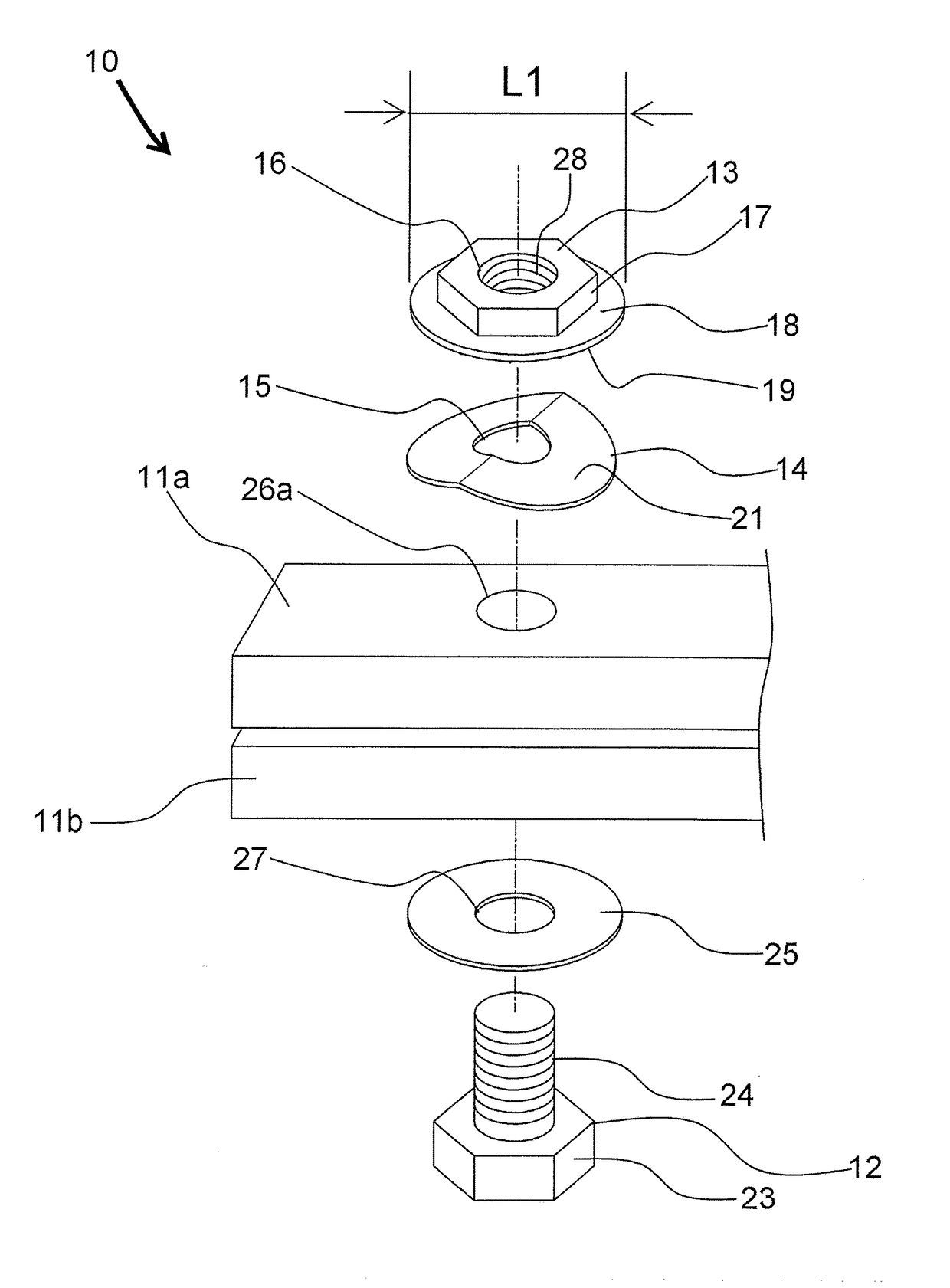
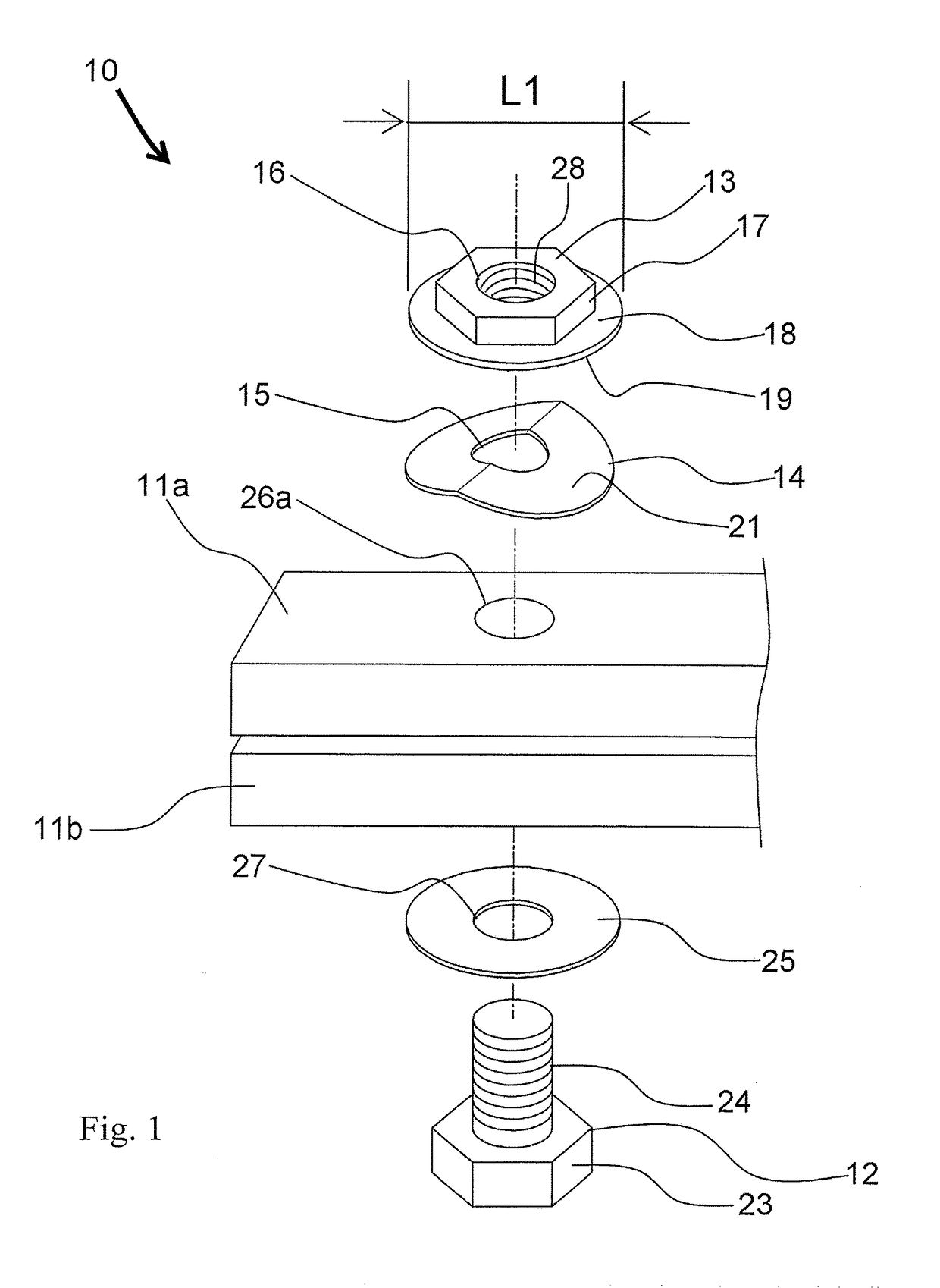
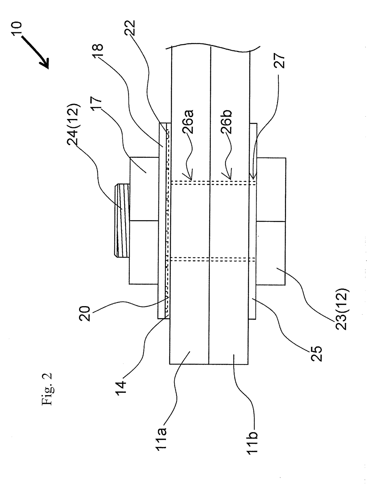
[0028]As illustrated in FIGS. 1 to 3, a fastening structure 10 according to one embodiment of the present invention includes a bolt 12 having a head portion 23 formed in a hexagonal pillar shape and a shaft portion 24 that extends from an end of the head portion 23 in the axial direction to form a substantially column shape having a thread formed on the outer periphery, a nut 13 that is screwed onto the bolt 12 to fasten a pair of target parts 11a and 11b each formed in a rectangular shape in a plan view and respectively provided with holes 26a and 26b, a washer 14 sandwiched between the target part 11a and the nut 13, and a washer 25 sandwiched between the target part 11b and the bolt 12.

[0029]As illustrated in FIGS. 1 to 3, the washers 14 and 25 according to the embodiment are each formed in a disk shape and respectively provided with holes 15 and 27 in which the bolt 1...


PUM


Abstract

A fastening structure includes a bolt, a nut screwed onto the bolt to fasten a target part, and a washer sandwiched between the target part and the nut. The washer is formed in a disk shape having a hole in which the bolt is inserted. The nut has a main body formed in a hexagonal pillar shape having a hole in which the bolt is inserted and a disk portion extending from an axial end of the main body. Protrusions are circumferentially distributed on a face of the disk portion, the face being on the side opposite the main body. The protrusions bite into a nut-side face of the washer to form meshed portions by screwing together the bolt and the nut.

Description

BACKGROUND[0001]Technical Field[0002]The present invention relates to a fastening structure for fastening a target part.[0003]Background of the Art[0004]Conventional tubular joints for connecting and fixing tubes used for liquid or gas transfer are known. Most of known types of tubular joints use bolts, nuts, and disks (washers) as means for fastening. Firmness and durability are more required of fixing of tubes than easy detachability. It is important that the fixed tubes maintain the engaged state without being affected by the change in temperature inside and outside the tubes and earthquakes.[0005]From the aforementioned view point, the applicant has searched out patent documents which are JP 4-10114 Y, JP 57-190120 Y, and JP 55-100710 Y. JP 4-10114 Y discusses a fastening structure using a screw (bolt), a disk (washer), and a nut. In the structure, the same number of lead waves are provided on a seating face of the anti-loosening nut in which the screw is inserted and the face o...

Claims


Application Information

Patent Timeline
IPC IPC(8): F16B39/34F16B39/24
CPCF16B39/24F16B39/34F16B39/26F16B39/282F16B43/00
Inventor NAGASHIMA, TAKESHIHIRASAWA, TORUKAMEDA, KAZUSHIGENAKAI, TETSUYAMORISAWA, SHINSUKESUZUKI, YUINAKAHARA, RYOYATAYA, YUTOMATSUDA, YUKIMORITA, MARIKOKAMATA, HIROMI
Owner NAGASHIMA FITTING CTD
Why Eureka
Try Eureka