Friction damper

a friction damper and damper technology, applied in the direction of shock absorbers, mechanical devices, transportation and packaging, etc., can solve the problems of insufficient control or amelioration of seismic forces of devices of any reasonable size, system not providing enough frictional force to effectively dampen seismically induced vibrations in structures, and designed to operate in one axial direction, so as to achieve control or amelioration of seismic energy

Inactive Publication Date: 2008-09-02
LEE GEORGE C +1
View PDF28 Cites 6 Cited by
  • Summary
  • Abstract
  • Description
  • Claims
  • Application Information

AI Technical Summary

Benefits of technology

[0013]To meet the mentioned need, a friction damper of the present invention generally comprises a channel member including at least one friction channel extending along a friction axis, and a wedge member including at least one corresponding friction wedge received by an associated friction channel for sliding motion along the friction axis relative to the channel member. Each friction channel has a pair of internal sidewalls connected by an internal transverse wall, wherein at least one of the pair of sidewalls forms an obtuse angle with the transverse wall. In a preferred construction, the sidewalls converge toward one another as they approach the connecting transverse wall in symmetric fashion about a centerline of the friction channel. The corresponding friction wedge includes a pair of external sidewalls parallel to the internal sidewalls of the channel, wherein the external sidewalls of the wedge are movable into respective surface-to-surface engagement with the internal sidewalls of the friction channel by adjusting the depth of receipt of the wedge in the friction channel. Preferably, each of the internal sidewalls of the friction channel forms an angle in the range from 93° through 102° with the transverse internal wall of the channel. The configuration of the present invention enables a large friction force to be generated using a modest normal force pushing the wedge deeper into the channel such that the sidewalls of the wedge engage the sidewalls of the channel. Frictional force can be increased by adding more contact surface area, for example by adding or enlarging plates. Frictional force can also be increased by increasing normal force through the addition of springs and the like, such as compression springs or other types of spring elements.
[0016]As a further feature of the present invention, the external sidewalls of the friction wedges can be maintained just out of engagement with the internal sidewalls of the friction channels by a plurality of shear keys designed to fail under predetermined loading conditions. Upon failure of the shear keys, such as may occur during an earthquake event, the wedges are forced deeper into the channels to bring about surface-to-surface engagement of the external sidewalls of a wedge with the internal sidewalls of a corresponding friction channel. Additionally, the friction damper of the present invention can be installed in series with a clutch mechanism designed to allow limited thermal expansion and contraction displacements between the isolated structural members without engagement of the friction damper.

Problems solved by technology

It is clear that such a device, of any reasonable size, would be insufficient in controlling or ameliorating seismic forces.
The described system does not provide enough frictional force to effectively dampen seismically induced vibrations in structures, or to mitigate other very large forces.
A drawback of this device, from the standpoint of seismic energy dissipation, is that it is designed to operate in one axial direction only.

Method used


Image

  • Friction damper
  • Friction damper
  • Friction damper

Examples


Embodiment Construction

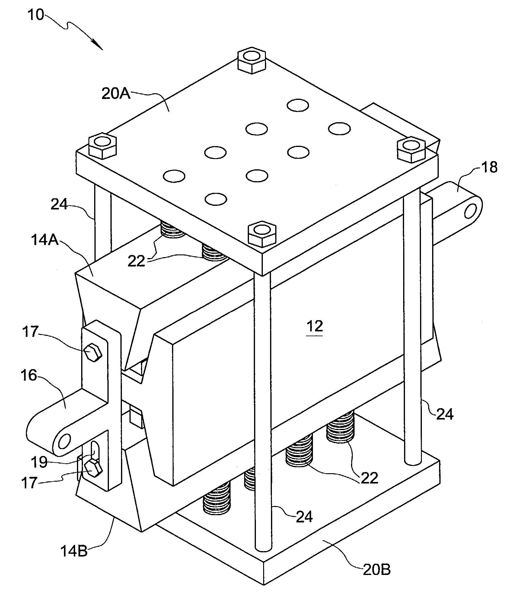
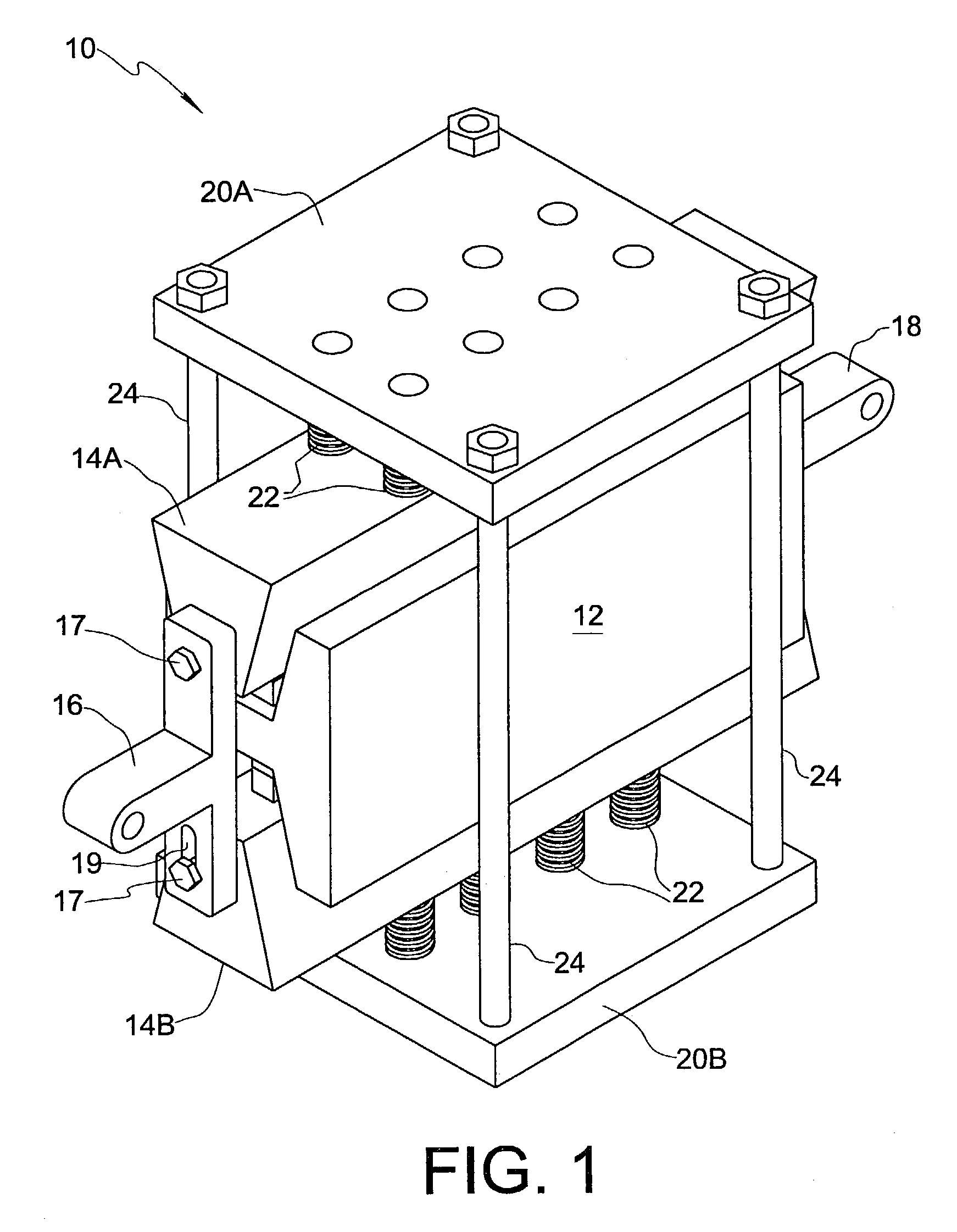
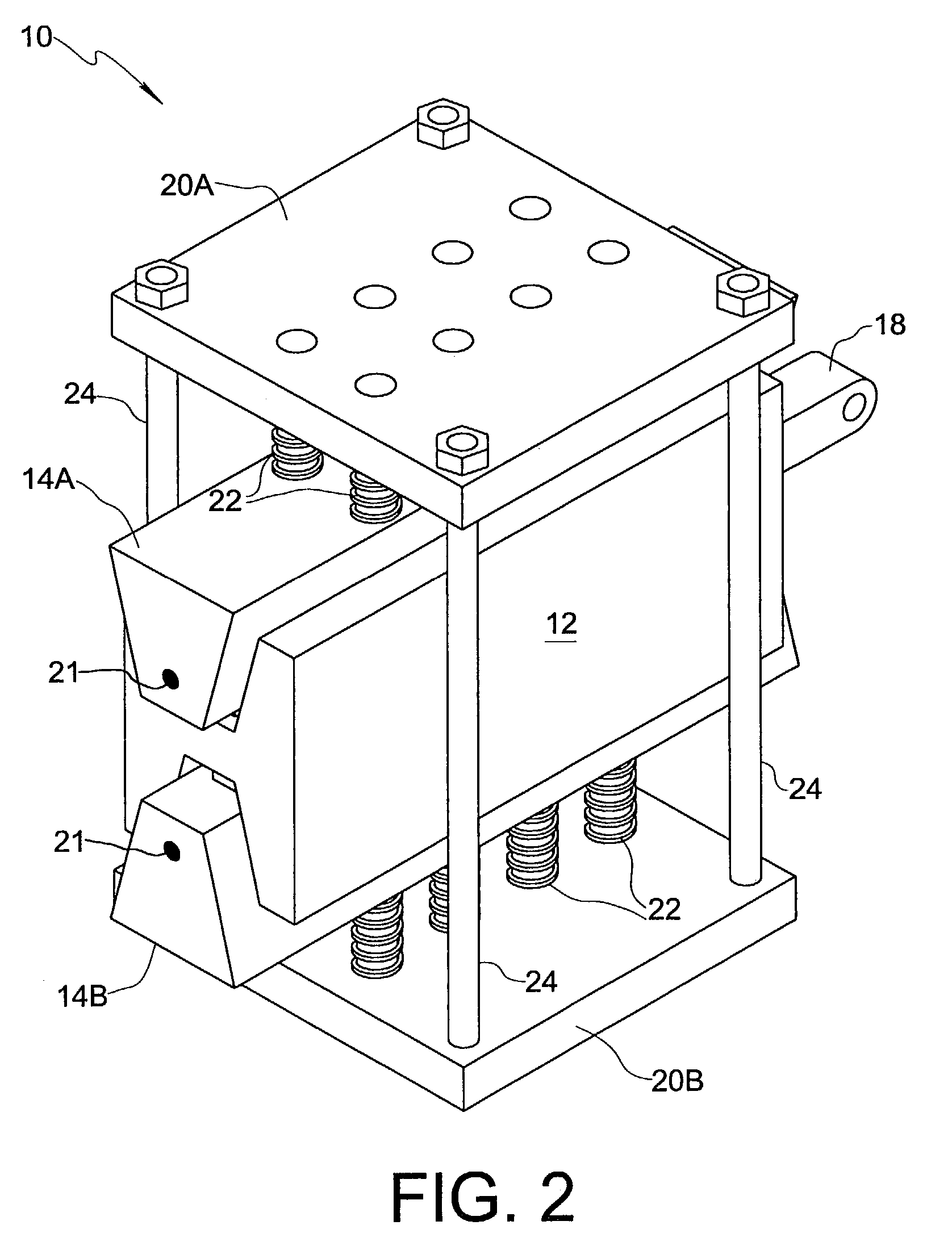
[0041]Referring initially to FIGS. 1 through 6 of the drawings, a friction damper 10 embodying the present invention in a basic form generally comprises a channel member 12 including a pair of friction channels 13A, 13B, and a pair of wedge members 14A, 14B themselves defining friction wedges respectively received by channels 13A, 13B. Channels 13A, 13B each include a pair of internal sidewalls 26 connected by an internal transverse wall 27. In the embodiment shown, both of the internal sidewalls 26 form an obtuse angle with transverse wall 27. Wedge members 14A, 14B each include a pair of external sidewalls 28 movable into respective surface-to-surface engagement with internal sidewalls 26 of the corresponding channel by adjusting depth of receipt of the wedge member in the friction channel. Channel member 12 and wedge members 14A, 14B are preferably formed of steel. The surfaces of internal sidewalls 26 and external sidewalls 28 act as the friction surfaces of friction bearing 10,...


PUM


Abstract

A friction damper comprises a channel member including at least one friction channel and a wedge member including at least one friction wedge received by a corresponding friction channel for sliding motion along the channel relative to the channel member. Each friction channel has a pair of internal sidewalls connected by an internal transverse wall, wherein at least one of the pair of sidewalls forms an obtuse angle with the transverse wall. In a preferred construction, the sidewalls are symmetrically convergent as they approach the connecting transverse wall. Each friction wedge includes a pair of external sidewalls parallel to the internal sidewalls of the channel, wherein the external sidewalls of the friction wedge are movable into surface-to-surface engagement with the internal sidewalls of the friction channel by adjusting the depth of receipt of the friction wedge in the friction channel. The friction damper of the present invention makes it possible to increase the equivalent friction coefficient by a factor of up to ten to twenty times.

Description

CROSS-REFERENCE TO RELATED APPLICATION[0001]This application is a continuation-in-part of U.S. application Ser. No. 09 / 994,148, filed Nov. 26, 2001, now abandoned, which is incorporated herein by reference.FIELD OF THE INVENTION[0002]The present invention relates generally to the field of energy dissipation devices for a variety of applications including dissipation of seismic energy.DESCRIPTION OF RELATED ART[0003]Friction dampers for use in earthquake vibration reduction are known. Friction dampers operate by converting kinetic energy, such as seismic vibration kinetic energy, into heat. In a friction damper, relative motion is created between contacting surfaces. Since friction dampers are mostly used in situations where the effects of relatively large forces are to be mitigated or constrained, there is a need for new friction dampers that are economical, compact and efficient in operation.[0004]One prior friction damper device is disclosed in International Publication No. WO 02 / ...

Claims


Application Information

Patent Timeline
Patent Type & Authority Patents(United States)
IPC IPC(8): F16F11/00F16F15/02E04H9/02F16F7/08F16F15/04
CPCF16F7/082E04H9/023E04H9/021
Inventor LEE, GEORGE C.LIANG, ZACH
Owner LEE GEORGE C
Why Eureka
Try Eureka