
Card edge connector

a card edge and connector technology, applied in the direction of coupling contact members, coupling device connections, connection contact member materials, etc., can solve the problems of insufficient locking effect of the latch piece, inability to press and lock the electric card positively, and the electric card cannot be inserted onto the insulating body firmly, etc., to achieve the effect of increasing the locking

Inactive Publication Date: 2007-11-22
MOLEX INC
View PDF5 Cites 5 Cited by
  • Summary
  • Abstract
  • Description
  • Claims
  • Application Information

AI Technical Summary

Benefits of technology

[0004] The primary object of the present invention is to provide a card edge connector in which the locking portion of the metallic piece can press and lock the electric card positively, thereby increasing the locking effect and preventing the electric card from becoming loose and bounding upwardly.
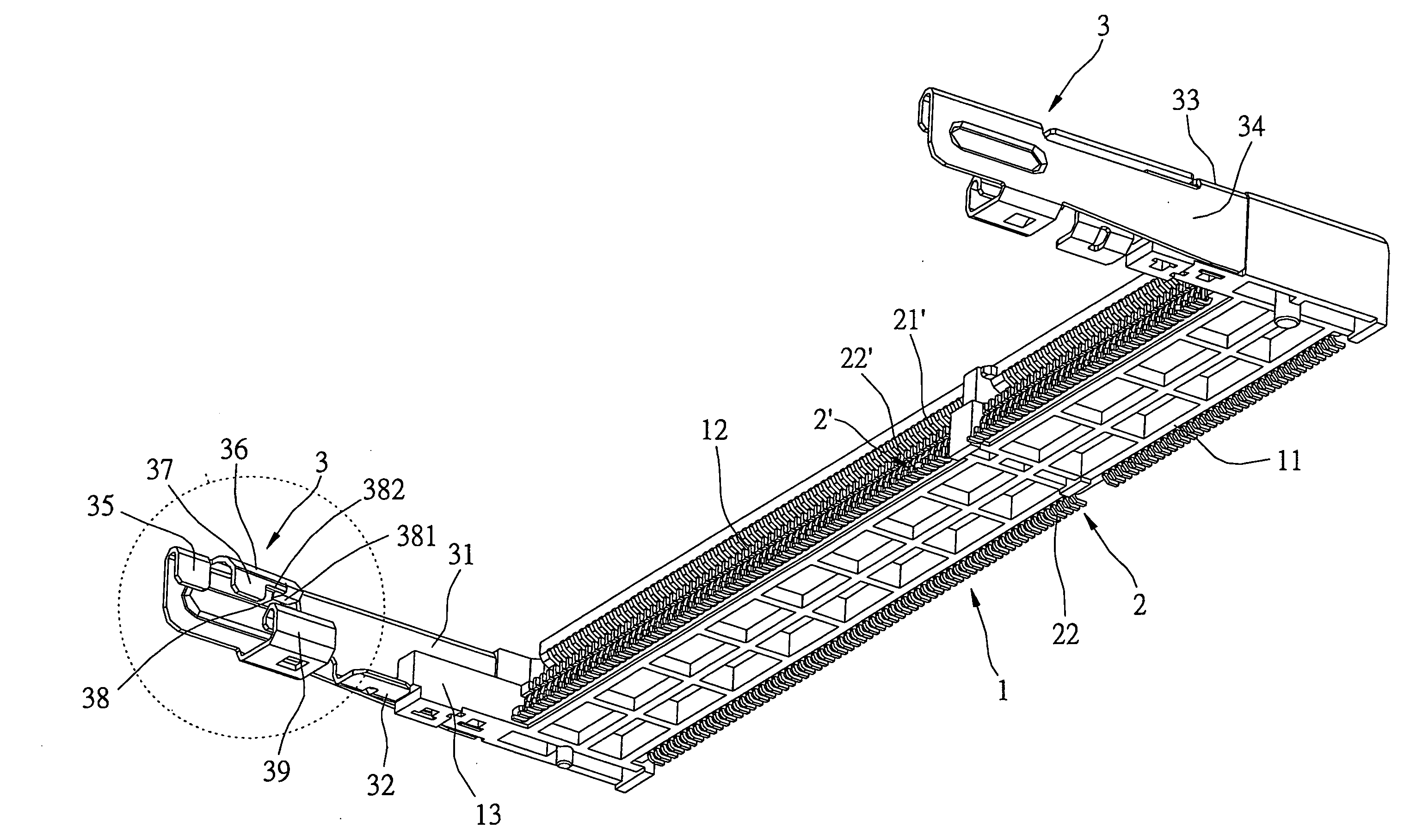
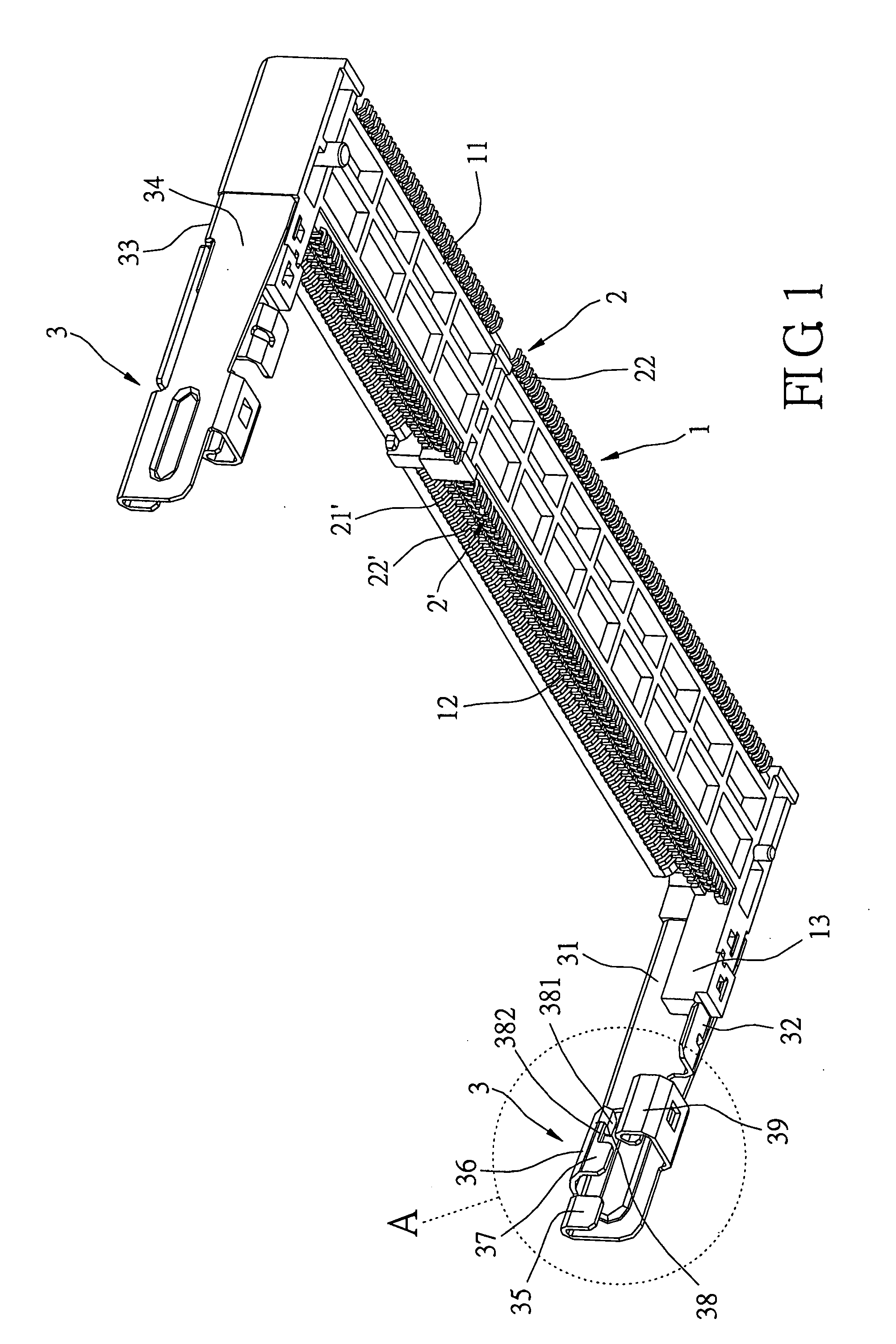
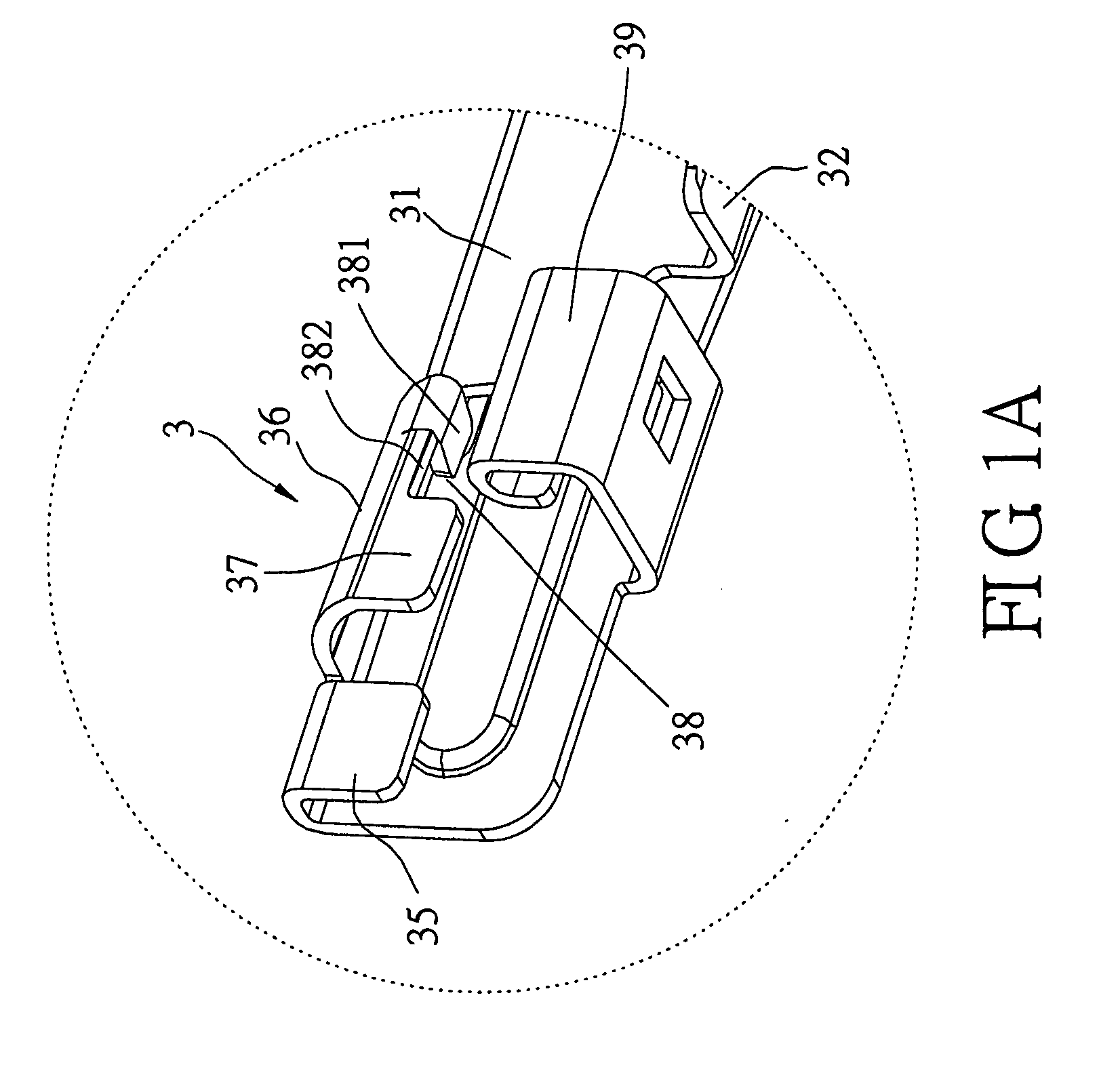
[0006] The advantages of the present invention lies in that the locking portion of the metallic piece is provided with a smooth bottom surface. The smooth bottom surface is adjacent to one side of the curved bottom surface. When locking, the curved bottom surface of the locking portion presses and locks the electric card. When the curved bottom surface is loosened due to the vibration of the electric card, the rear end of the electric card is raised so that it becomes inclined. At this time, the smooth bottom surface of the locking portion is brought into contact with the electric card. The smooth bottom surface increases the friction force, thereby generating a larger friction force between the locking portion and the electric card. Therefore, the locking effect is increased, preventing the electric card from becoming loose and bounding upwardly.

Problems solved by technology

Although the above card edge connector is provided with the latch piece for locking the electric card, the latch piece is a curved piece that is prone to loosening due to the vibrations of the electric card.
Thus, the locking effect of the latch piece is insufficient to press and lock the electric card positively.
As a result, the electric card is prone to loosening and bounding upwardly so that the electric card cannot be inserted onto the insulating body firmly.

Method used


Image

  • Card edge connector
  • Card edge connector
  • Card edge connector

Examples


Embodiment Construction

[0017] Please refer to FIGS. 1, 1A, 2 and 2A, in which the present invention of a card edge connector is shown. The card edge connector is provided on an upper surface of a circuit board 5 and allows an electric card 6 to be inserted therein, thereby electrically connecting the circuit board 5 and the electric card 6. The card edge connector comprises an insulating body 1, a plurality of terminals 2, 2′ and two metallic pieces 3. The insulating body 1 is made of plastic materials and has a body portion 11. The body portion 11 is provided thereon with an elongated insertion slot 12 that allows the electric card 6 to be inserted therein. A fixing block 13 extends from both sides of the body portion 11 respectively. The two fixing blocks 13 are blocks protruding from the front side of the body portion 11. Each of the two fixing blocks 13 is formed thereon with two insertion holes 16, as shown in FIG. 5.

[0018] The terminals 2, 2′ are provided on the body portion 11 of the insulating bo...


PUM


Abstract

A card edge connector that allows the insertion of an electric card includes an insulating body, a plurality of terminals, and two metallic pieces. Each of the two metallic pieces includes a substrate, an elastic arm connected to the substrate, and a locking portion connected to the upper edge of the free end of the elastic arm. The locking portion has a curved bottom surface and a smooth bottom surface. The smooth bottom surface is adjacent to the curved bottom surface. When locked, the curved bottom surface of the locking portion presses and locks the electric card. When the curved bottom surface loosens due to vibrations of the electric card, the smooth bottom surface of the locking portion presses and locks the electric card firmly. Therefore, the locking effect is increased, and the electric card is prevented from loosening and bounding upwardly.

Description

FIELD OF THE INVENTION [0001] The present invention relates to a card edge connector, and in particular to a card edge connector provided on the upper surface of a circuit board that allows an electric card to be inserted therein. BACKGROUND OF THE INVENTION [0002] A conventional card edge connector is provided on the upper surface of a circuit board and allows an electric card to be inserted therein, thereby electrically connecting the circuit board and the electric card. Taiwan Patent Publication No. 382836 (Application No. 86118731) published on Feb. 21, 2000 discloses an electrical connector having a metallic latch, which includes a dielectric casing and a latching element having a latch piece. The latch piece of the latching element can be locked to the upper surface of the electric card, thereby preventing an upward bound of the electric card. In this way, the electric card can be inserted on the dielectric casing stably. [0003] Although the above card edge connector is provid...

Claims


Application Information

Patent Timeline
Patent Type & Authority Applications(United States)
IPC IPC(8): H01R13/44
CPCH01R13/639H01R13/635
Inventor HO, YI-TSE
Owner MOLEX INC
Learn More