Reclining device and method of locking the device

a technology of locking device and reclining mechanism, which is applied in the direction of movable seats, vehicle components, vehicle arrangements, etc., can solve the problems of increasing size, weight and manufacturing cost of reclining mechanism, tooth slippage, and limited relative rotation of both housings, so as to improve the locking performance of the conventional reclining mechanism without increasing the spring force

Inactive Publication Date: 2005-12-01
TOYOTA BOSHOKU KK
View PDF12 Cites 22 Cited by
  • Summary
  • Abstract
  • Description
  • Claims
  • Application Information

AI Technical Summary

Benefits of technology

[0005] It is one object of the present teachings to eliminate the so-called “tooth slippage” at the time that the respective pawls engage the ratchets, thereby improving the locking performance of the conventional reclining mechanism without increasing the spring force.
[0007] According to the utilization of such a construction, when each of the slide pawls moves by the spring force from the free position to the locking position, in its initial state, the spring force can converge on one of the slide pawls, for example, the slide pawl having a preceeding ed movement start timing. Therefore, the engagement (locking) force between one of the slide pawls and the ratchet can be increased without increasing the spring force. As a result, so-called “tooth slippage” may be eliminated so that the locking performance of the reclining mechanism can be increased.

Problems solved by technology

As a result, the relative rotation of both of the housings is limited so that the reclining mechanism is configured in a locking condition.
Therefore, the engagement (locking) force between the respective pawls and the ratchets is insufficient, thereby causing so-called “tooth slippage” so that actual engagement portions are shifted one or two teeth from target engagement portions.
However, increasing of the spring force may result in increasing size, weight and manufacturing cost of the reclining mechanism.

Method used


Image

  • Reclining device and method of locking the device
  • Reclining device and method of locking the device
  • Reclining device and method of locking the device

Examples


first embodiment

[0026] Hereinafter, embodiments of the present invention will be described. A first embodiment will be described with reference to FIGS. 1 to 7.

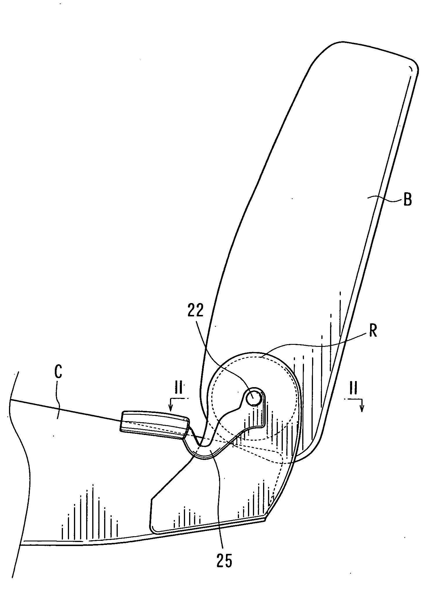
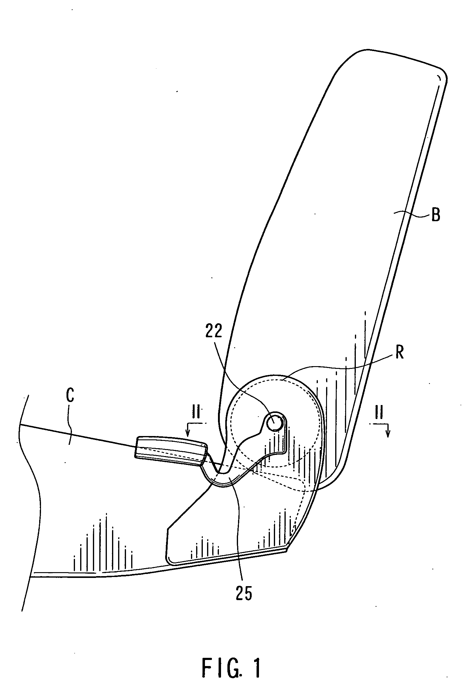
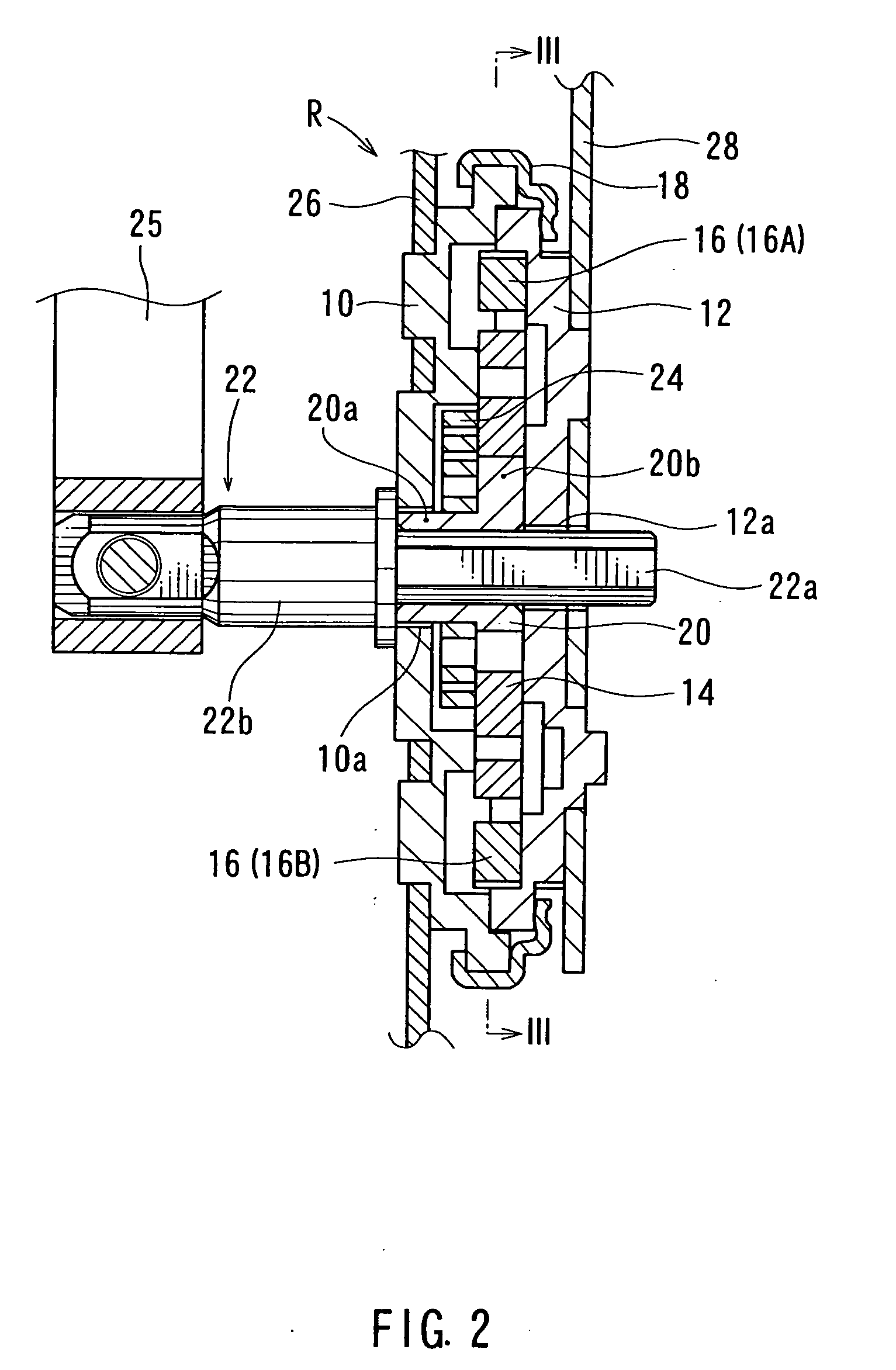
[0027]FIG. 1 is a partially omitted side view of a vehicle seat. FIG. 2 is an enlarged cross-sectional view taken along line II-II in FIG. 1. FIGS. 3-7 are plan views of FIG. 2 viewed along line III-III. As shown in FIG. 1, a rear end of a seat cushion C of a seat is connected to a lower end of a seat back B via a reclining mechanism R. The reclining mechanism R can be unlocked by operating an operation lever 25 so that the seat back B can be tilted back and forth around an operating shaft 22.

[0028] As shown in FIGS. 2 to 3, the reclining mechanism R includes an outer shell that is constructed from a disk-shaped stationary housing 10 and a disk-shaped rotational housing 12. The housings 10 and 12 are oppositely coupled to each other and are relatively rotatably connected by clamping a clip ring 18 that is circumferentially attached thereto ...

second embodiment

[0048] Next, the second embodiment will be described with reference to FIG. 8.

[0049]FIG. 8 is a plan view corresponding to FIG. 3 and illustrates a reclining mechanism according to the second embodiment. As will be apparent from this drawing, in the third embodiment, the present invention is applied to a reclining mechanism R that includes a rotating-type operating cam and three slide pawls.

[0050] In FIG. 8, the circular plate-shaped operating cam 114 is positioned in the stationary housing 10 so as to rotate around an axis of an operating shaft 122. Also, the three slide pawls 116 (116A, 116B, 116C) are positioned in pawl guide grooves of the stationary housing 10 so as to radially slide without circumferentially moving. Each of cam portions 114c, 114d and 114e formed in an outer circumferential surface of the operating cam 114 are positioned so as to contact or to be contactable with contact portions 116b of each of the slide pawls 116. The operating cam 114 is rotatably supporte...


PUM


Abstract

The present invention relates to a reclining mechanism having a construction in which a plurality of pawls are received in a pair of housings that are relatively rotatably connected to each other, each of these pawls being prevented from rotating relative to one of said housings and being engageable with a ratchet formed in the other of said housings, each of said pawls being moved by a spring force from a free position in which the relative rotation of said housings is permitted to a locking position in which the relative rotation of said housings is prevented by virtue of engagement of the pawl and said ratchet, wherein at least one of the pawls is moved prior to the other of the pawls when each of said pawls moves from said free position to said locking position. According to utilization of such a construction, when each of the slide pawls moves by the spring force from the free position to the locking position, in its initial state, the spring force can converge on one of the slide pawls, for example, the slide pawl having a preceding movement start timing. Therefore, the engagement (locking) force between one of the slide pawls and the ratchet can be increased without increasing the spring force. As a result, so-called “tooth slippage” may be eliminated so that the locking performance of the reclining mechanism can be increased.

Description

TECHNICAL FIELD OF THE INVENTION [0001] The present invention mainly relates to seat reclining mechanisms for a vehicle seat and locking methods of the same RELATED ART [0002] Conventionally, such a seat reclining mechanism is taught, for example, by Japanese Laid-Open Patent Publication No. 2000-79032. In this seat reclining mechanism, a stationary housing and a rotational housing are relatively rotatably connected. The stationary and rotational housings define an inner space therebetween in which a pair of pawls and an operating cam are respectively received. Both of the pawls can radially move while they are prevented from rotating relative to the stationary housing. Also, both of the pawls have toothed portions that can engage inner toothed portions formed in an inner circumferential surface of the rotational housing. The inner toothed portions of the rotational housing will be hereinafter referred to as “ratchets.”[0003] When an operating shaft is operated so as to be rotated, ...

Claims


Application Information

Patent Timeline
Patent Type & Authority Applications(United States)
IPC IPC(8): B60N2/235
CPCB60N2/2356B60N2/236
Inventor URAMICHI, HIDEKIOTSUKA, TAIYO
Owner TOYOTA BOSHOKU KK
Why Eureka
Try Eureka