Magnetic head for perpendicular magnetic recording with a coil including a first winding portion of one turn and a second winding portion of less than one turn

a perpendicular magnetic and recording technology, applied in the direction of magnetic recording heads, data recording, instruments, etc., can solve the problems of insufficient shortening of the second magnetic head and inability to provide a sufficiently large magnetomotive force, and achieve a sufficient reduction in the length of the magnetic path and sufficient magnetomotive force

Active Publication Date: 2017-05-04
HEADWAY TECH INC
View PDF0 Cites 1 Cited by
  • Summary
  • Abstract
  • Description
  • Claims
  • Application Information

AI Technical Summary

Benefits of technology

[0019]According to the present invention, no portion of the coil except the first coil element lies in the first space. The present invention thus allows a sufficient reduction in length of the magnetic path passing through the first return path section provided on the trailing side of the main pole and through the main pole. Further, according to the present invention, the coil includes the first winding portion of one turn and the second winding portion of less than one turn. This allows the coil to provide a sufficiently large magnetomotive force.

Problems solved by technology

For the first magnetic head, however, the coil is unable to provide a sufficiently large magnetomotive force.
Thus, it is not possible for the second magnetic head to sufficiently shorten the magnetic path passing through the return path section and the main pole.

Method used


Image

  • Magnetic head for perpendicular magnetic recording with a coil including a first winding portion of one turn and a second winding portion of less than one turn
  • Magnetic head for perpendicular magnetic recording with a coil including a first winding portion of one turn and a second winding portion of less than one turn
  • Magnetic head for perpendicular magnetic recording with a coil including a first winding portion of one turn and a second winding portion of less than one turn

Examples


first embodiment

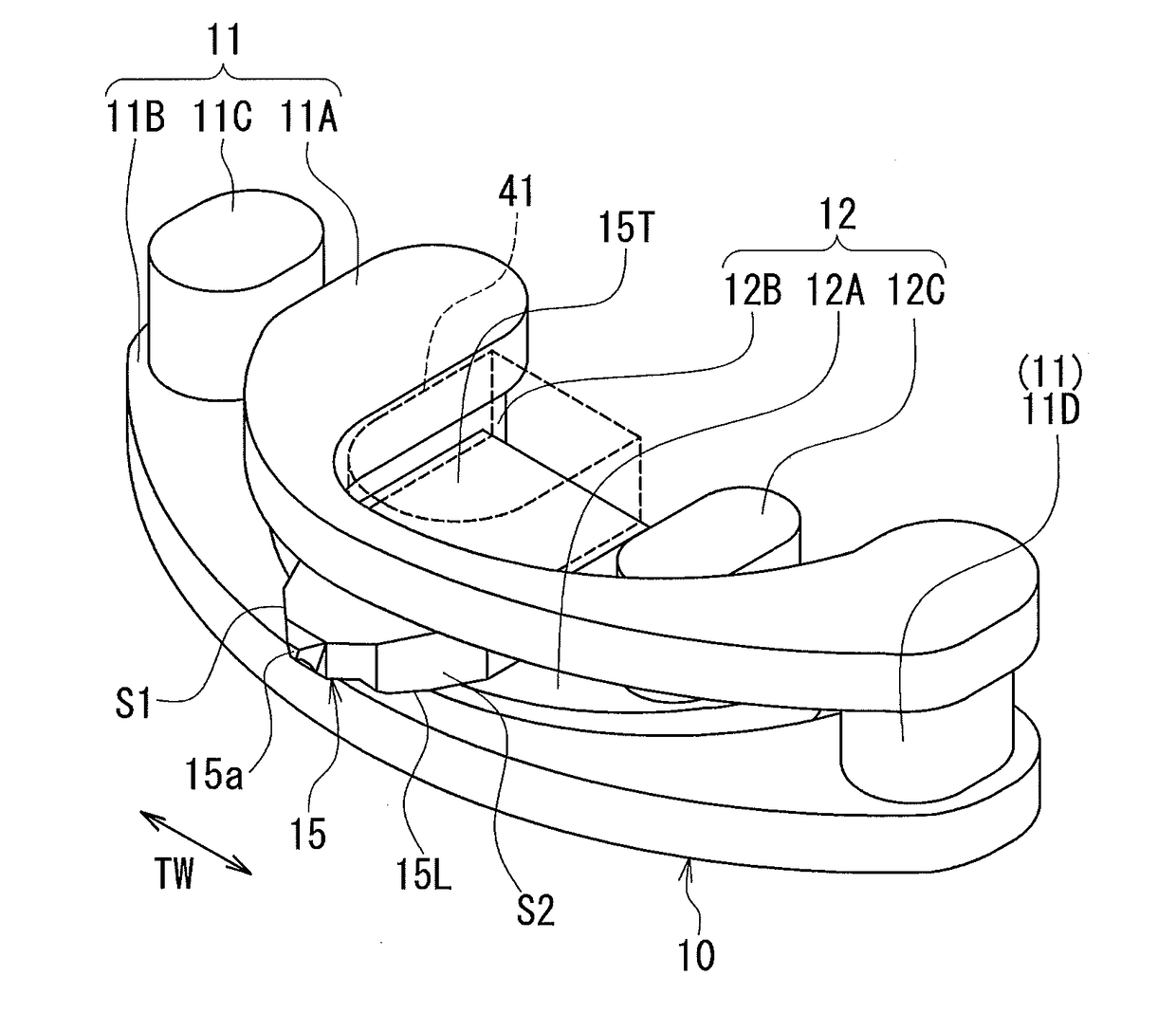
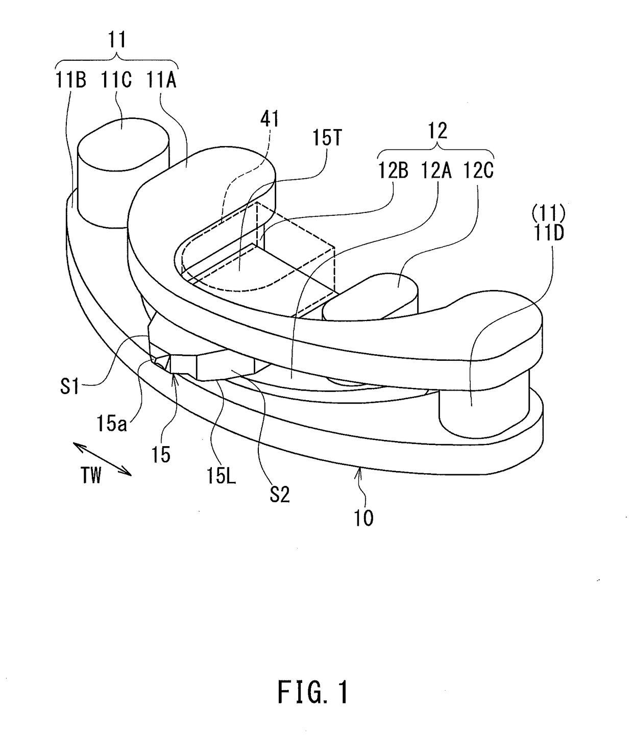
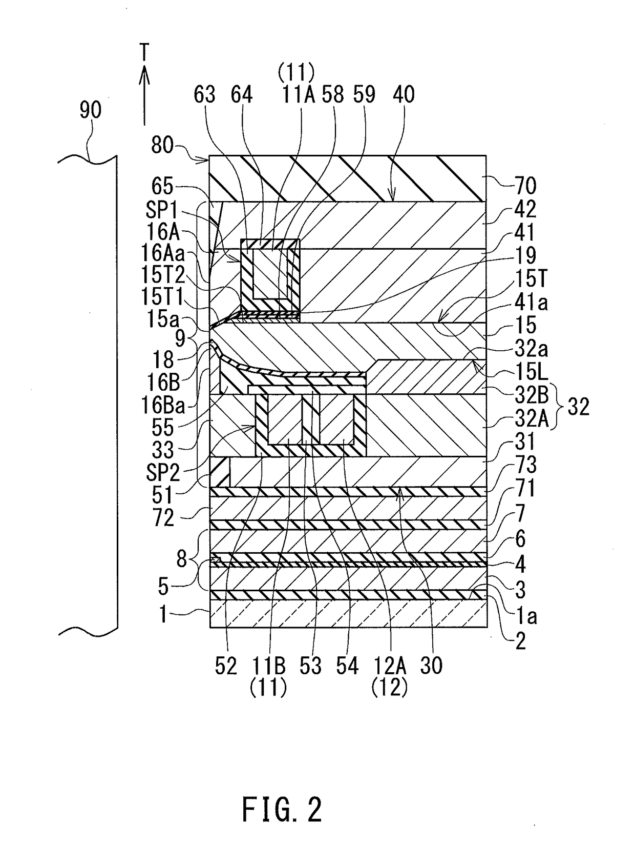
[0034]Preferred embodiments of the present invention will now be described in detail with reference to the drawings. First, reference is made to FIG. 1 to FIG. 6 to describe the configuration of a magnetic head for perpendicular magnetic recording (hereinafter simply referred to as magnetic head) according to a first embodiment of the invention. FIG. 1 is a perspective view showing the main part of the magnetic head according to the present embodiment. FIG. 2 is a cross-sectional view of the magnetic head according to the present embodiment. The arrow labeled T in FIG. 2 indicates the direction of travel of a recording medium. FIG. 3 is a front view showing the medium facing surface of the magnetic head according to the present embodiment. FIG. 4 is a plan view showing a second and a third coil element of the magnetic head according to the present embodiment. FIG. 5 is a plan view showing a main pole of the magnetic head according to the present embodiment. FIG. 6 is a plan view sho...

second embodiment

[0091]A magnetic head according to a second embodiment of the present invention will now be described with reference to FIG. 11 to FIG. 13. FIG. 11 is a cross-sectional view of the magnetic head according to the present embodiment. The arrow labeled T in FIG. 11 indicates the direction of travel of a recording medium. FIG. 12 is a plan view showing a third winding portion of the coil of the magnetic head according to the present embodiment. FIG. 13 is a plan view showing a first and a second winding portion of the coil of the magnetic head according to the present embodiment. In FIG. 12 and FIG. 13, the arrow labeled TW indicates the track width direction.

[0092]The magnetic head according to the present embodiment differs from the magnetic head according to the first embodiment in the following ways. The coil 10 of the present embodiment includes a first winding portion 21, a second winding portion 22 and a third winding portion 23, in place of the first winding portion 11, the seco...


PUM

PropertyMeasurementUnit
thicknessaaaaaaaaaa
thicknessaaaaaaaaaa
angleaaaaaaaaaa

Abstract

A magnetic head includes a coil, a main pole and a return path section. The return path section is located on the trailing side relative to the main pole so that a space is defined between the main pole and itself. The coil includes a first winding portion and a second winding portion connected in series. The first winding portion extends to pass through the aforementioned space, and extends once around the entire perimeter of the main pole as viewed from the medium facing surface. The second winding portion does not pass through the aforementioned space, and surrounds only a part of the entire perimeter of the main pole as viewed from the medium facing surface.

Description

BACKGROUND OF THE INVENTION[0001]1. Field of the Invention[0002]The present invention relates to a magnetic head for perpendicular magnetic recording for use to write data on a recording medium by means of a perpendicular magnetic recording system.[0003]2. Description of the Related Art[0004]The recording systems of magnetic read / write apparatuses include a longitudinal magnetic recording system in which the magnetization of signals is directed along the plane of a recording medium (the longitudinal direction), and a perpendicular magnetic recording system in which the magnetization of signals is directed perpendicular to the plane of a recording medium. It is known that the perpendicular magnetic recording system is harder to be affected by thermal fluctuation of the recording medium and capable of providing higher linear recording density, compared with the longitudinal magnetic recording system.[0005]Magnetic heads for perpendicular magnetic recording typically have, like those f...

Claims


Application Information

Patent Timeline
Patent Type & Authority Applications(United States)
IPC IPC(8): G11B5/127G11B5/39
CPCG11B5/3123G11B5/1278G11B5/17
Inventor SASAKI, YOSHITAKAITO, HIROYUKISATO, KAZUKIIKEGAWA, YUKINORITANEMURA, SHIGEKITAKANO, KENICHI
Owner HEADWAY TECH INC
Why Eureka
Try Eureka