Thin-film magnetic head and method of manufacturing same

Active Publication Date: 2006-06-13
HEADWAY TECH INC +1
View PDF8 Cites 2 Cited by
  • Summary
  • Abstract
  • Description
  • Claims
  • Application Information

AI Technical Summary

Benefits of technology

[0022]It is an object of the invention to provide a thin-film magnetic head which is small in magnetic path length and thus excellent in reco

Problems solved by technology

Under the circumstances, the conventional thin-film magnetic heads have had the problem that the thin-film coil increases in resistance when the yoke length is reduced to improve the recording characteristics at high frequency bands.
As the resistance of the thin-film coil increases, there arises a problem that the magnetic pole portions can protrude toward the recording medium due to heat occurring from the thin-film coil so that the magnetic pole portions are more likely to collide with the recording medium.
Thus, in the conventional thin-film magnetic heads, it has been unfeasible to reduce the yoke length considerably from the viewpoint of avoiding the problem that occurs from an increase in the resistance of the thin-film coil.
The

Method used


Image

  • Thin-film magnetic head and method of manufacturing same
  • Thin-film magnetic head and method of manufacturing same
  • Thin-film magnetic head and method of manufacturing same

Examples


first embodiment

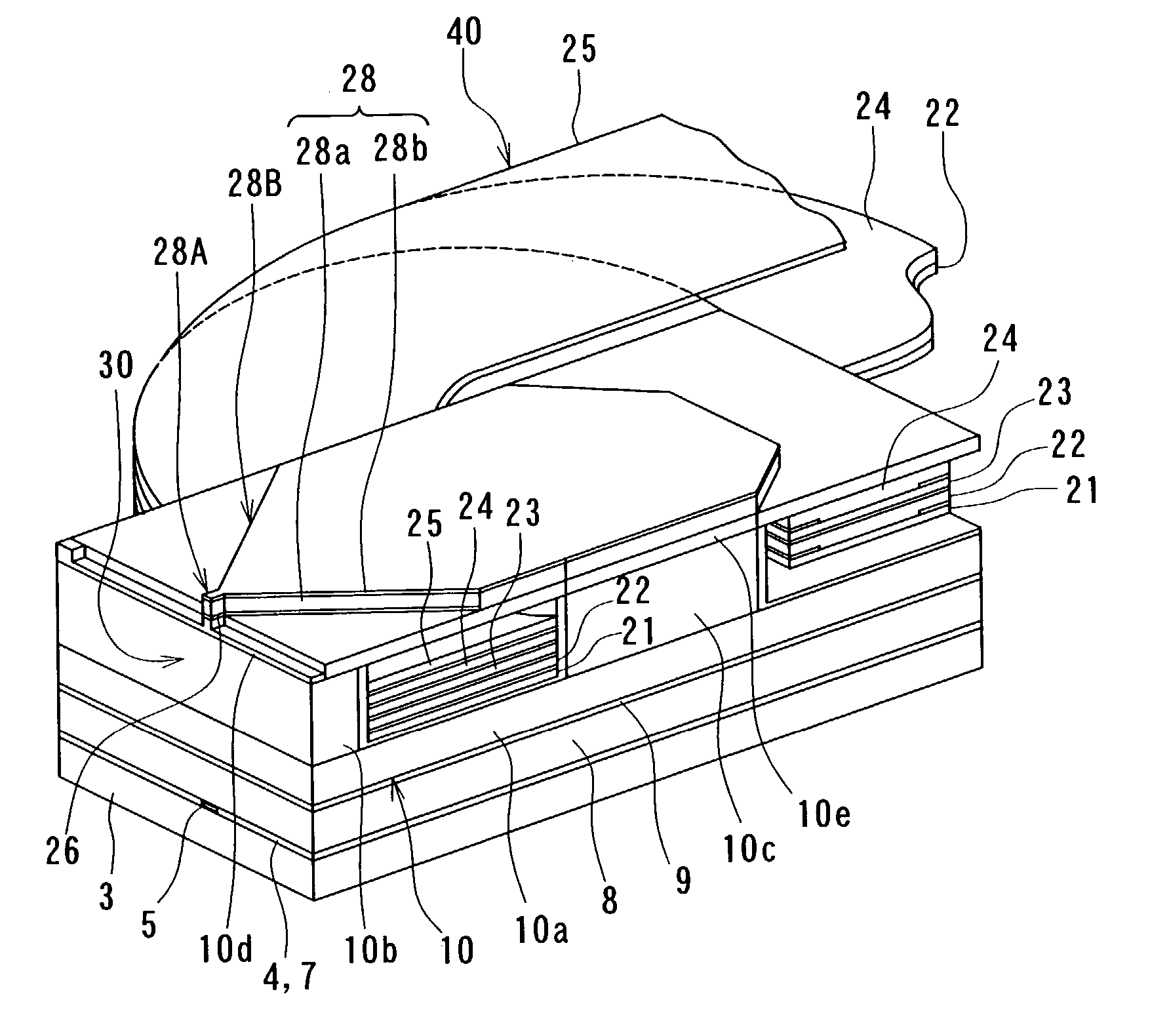
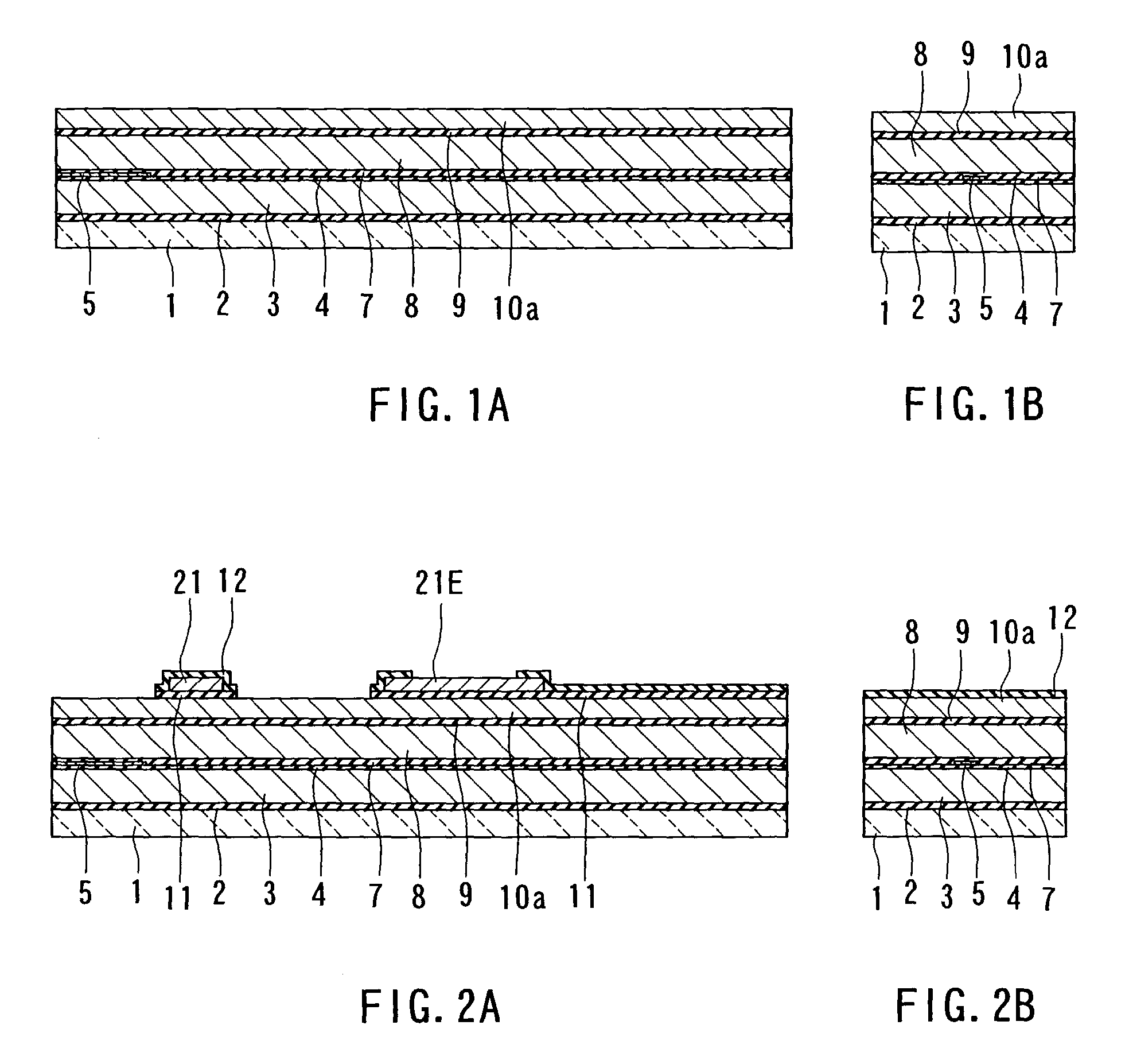
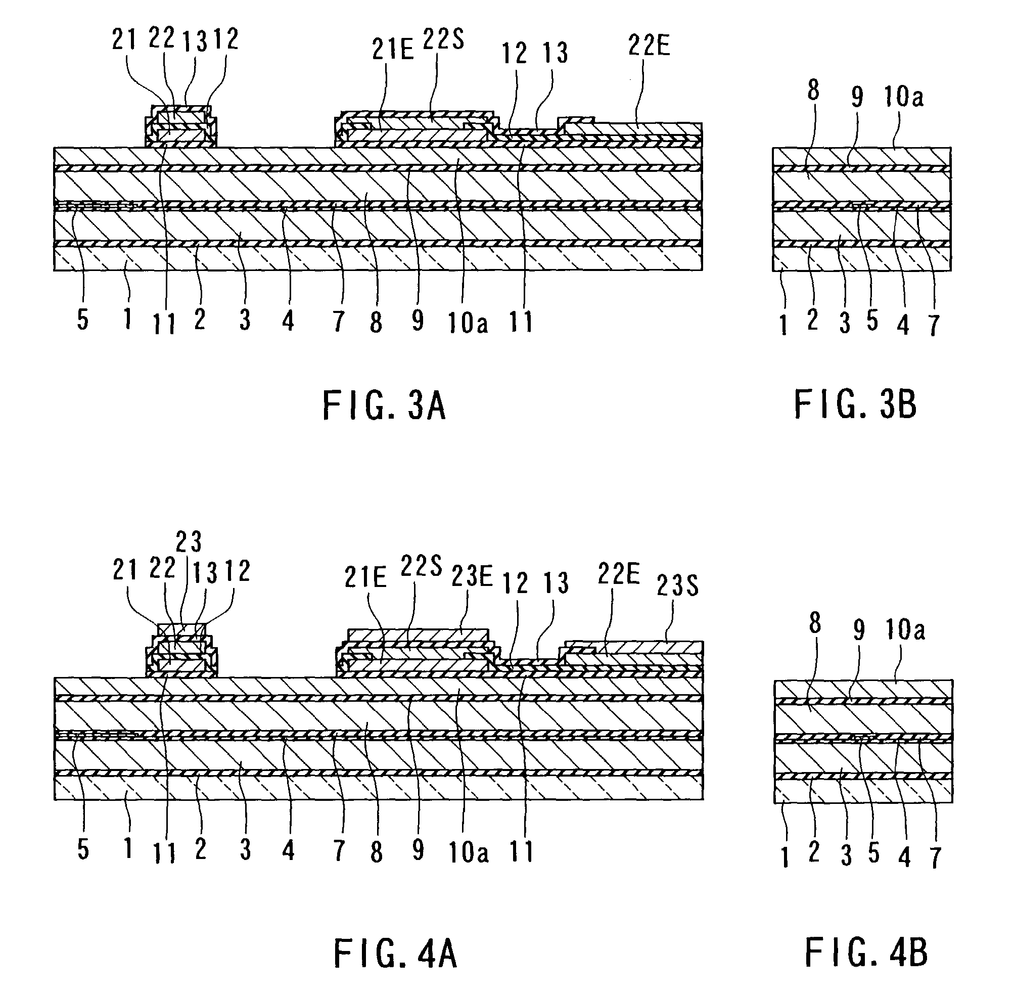
[0128]First, a method of manufacturing a thin-film magnetic head according to a first embodiment of the invention will now be described with reference to FIGS. 1A to 14A, FIGS. 1B to 14B, and FIG. 15 to FIG. 20. FIGS. 1A to 14A are cross sections each orthogonal to the air bearing surface and the top surface of the substrate. FIGS. 1B to 14B are cross sections of the magnetic pole portion each parallel to the air bearing surface. FIG. 15 is a perspective view showing the thin-film magnetic head according to the present embodiment excluding an overcoat layer. FIG. 16 to FIG. 20 are plan views for explaining the method of forming a thin-film coil of the present embodiment.

[0129]In the method of manufacturing the thin-film magnetic head of the present embodiment, as shown in FIGS. 1A and 1B, an insulating layer 2 made of alumina (Al2O3), for example, is first deposited to a thickness of about 1 to 3 μm on a substrate 1 made of aluminum oxide and titanium carbide (Al2O3—TiC), for exampl...

second embodiment

[0199]Now, a thin-film magnetic head and a method of manufacturing the same according to a second embodiment of the invention will be described with reference to FIGS. 30A to 40A, FIGS. 30B to 40B, and FIGS. 41 to 45. FIGS. 30A to 40A are cross sections each orthogonal to the air bearing surface and the top surface of the substrate. FIGS. 30B to 40B are cross sections of the magnetic pole portion each parallel to the air bearing surface. FIGS. 41 to 45 are plan views for explaining the method of forming a thin-film coil of the present embodiment.

[0200]The method of manufacturing the thin-film magnetic head according to the present embodiment is the same as that of the first embodiment up to the step of forming the first layer 10a of the bottom pole layer 10 as shown in FIGS. 30A and 30B. The material, thickness, and forming method of the first layer 10a are the same as in the first embodiment. Here, by way of example, the first layer 10a shall be formed of CoFeN to a thickness of 0....

third embodiment

[0235]Now, a method of manufacturing a thin-film magnetic head according to a third embodiment of the invention will be described with reference to FIGS. 46A to 62A, FIGS. 46B to 62B, and FIGS. 63 to 66. FIGS. 46A to 62A are cross sections each orthogonal to the air bearing surface and the top surface of the substrate. FIGS. 46B to 62B are cross sections of the magnetic pole portion each parallel to the air bearing surface. FIGS. 63 to 66 are plan views for explaining the method of forming a thin-film coil of the present embodiment.

[0236]In the method of manufacturing the thin-film magnetic head of the present embodiment, as shown in FIGS. 46A and 46B, an insulating layer 2 made of alumina (Al2O3), for example, is first deposited to a thickness of about 2 to 5 μm on a substrate 1 made of aluminum oxide and titanium carbide (Al2O3—TiC), for example. On the insulating layer 2, a bottom shield layer 3 of a magnetic material such as Permalloy (NiFe) is formed to a thickness of about 2 t...


PUM


Abstract

A thin-film magnetic head includes a bottom pole layer, a top pole layer, a recording gap layer, and a thin-film coil. The bottom pole layer has first to fifth layers. The third layer and the fifth layer constitute a coupling portion for establishing magnetic coupling between the bottom pole layer and the top pole layer. The thin-film coil has first to fifth layer portions each of which is made of a flat conductive layer of a single turn. The first to fifth layer portions are laminated, and connected in series to each other. The coupling portion has an end face facing toward the air bearing surface. The end face includes a curved surface convex toward the medium facing surface.

Description

BACKGROUND OF THE INVENTION[0001]1. Field of the Invention[0002]The present invention relates to a thin-film magnetic head having at least an induction-type electromagnetic transducer, and a method of manufacturing same.[0003]2. Description of the Related Art[0004]Recent years have seen significant improvements in the areal recording density of hard disk drives. In particular, areal recording densities of latest hard disk drives reach 80 to 100 GB / platter and are even on a pace to exceed that level. Thin-film magnetic heads are required of improved performance accordingly.[0005]Among the thin-film magnetic heads, widely used are composite thin-film magnetic heads made of a layered structure including a recording head having an induction-type electromagnetic transducer for writing and a reproducing head having a magnetoresistive element (that may be hereinafter called an MR element) for reading.[0006]In general, a recording head incorporates: a medium facing surface (air bearing surf...

Claims


Application Information

Patent Timeline
IPC IPC(8): G11B5/147G11B5/17G11B5/31G11B5/39
CPCB82Y10/00B82Y25/00G11B5/3116G11B5/3163G11B5/3909G11B5/3967G11B5/313G11B5/17G11B2005/3996
Inventor SASAKI, YOSHITAKAKAMIGAMA, TAKEHIRO
Owner HEADWAY TECH INC
Why Eureka
Try Eureka