Thin-film magnetic head and method of manufacturing same

Active Publication Date: 2005-04-07
HEADWAY TECH INC
View PDF7 Cites 14 Cited by
  • Summary
  • Abstract
  • Description
  • Claims
  • Application Information

AI Technical Summary

Benefits of technology

[0024] It is an object of the invention to provide a thin-film magnetic head which is small in magnetic path length and thus excellent in recording characteristics at high frequency bands and which also has a thin-film coil of small resistance, and a method of manufacturing the same.
[0031] In the thin-film magnetic head of the invention, the coupling portion has an end face facing toward the medium facing surface, and this end face includes a curved surface convex toward the medium facing surface. A part of the thin-film coil is disposed between the end face of the coupling portion and the medium facing surface, and has a minimum width of the thin-film coil in a position on a virtual line connecting the end face of the coupling portion and the medium facing surface in the shortest distance. The part of the thin-film coil includes a variable width portion that increases in width with distance from the virtual line. Consequently, according to the thin-film magnetic head of the invention, it is possible to reduce the resistance of the thin-film coil while shortening the magnetic path length.
[0053] In the first method of manufacturing a thin-film magnetic head of the invention, one of the step of forming the first pole layer and the step of forming the second pole layer may include the step of forming the coupling portion so that the coupling portion has an end face facing toward the medium facing surface and the end face includes a curved surface convex toward the medium facing surface. A part of the thin-film coil is disposed between the end face of the coupling portion and the medium facing surface, and has a minimum width of the thin-film coil in a position on a virtual line connecting the end face of the coupling portion and the medium facing surface in the shortest distance. The part of the thin-film coil includes a variable width portion that increases in width with distance from the virtual line. Consequently, in the thin-film magnetic head, it is possible to reduce the resistance of the thin-film coil while shortening the magnetic path length.
[0068] In the second method of manufacturing a thin-film magnetic head of the invention, the coupling portion has an end face facing toward the medium facing surface, and this end face includes a curved surface convex toward the medium facing surface. A part of the first coil and a part of the second coil are both disposed between the end face of the coupling portion and the medium facing surface, and have a minimum width of the thin-film coil in a position on a virtual line connecting the end face of the coupling portion and the medium facing surface in the shortest distance. The part of the first coil and the part of the second coil include respective variable width portions that increase in width with distance from the virtual line. Consequently, in the thin-film magnetic head, it is possible to reduce the resistance of the thin-film coil while shortening the magnetic path length.

Problems solved by technology

Under the circumstances, the conventional thin-film magnetic heads have had the problem that the thin-film coil increases in resistance when the yoke length is reduced to improve the recording characteristics at high frequency bands.
As the resistance of the thin-film coil increases, there arises a problem that the magnetic pole portions can protrude toward the recording medium due to heat occurring from the thin-film coil so that the magnetic pole portions are more likely to collide with the recording medium.
Thus, in the conventional thin-film magnetic heads, it has been unfeasible to reduce the yoke length considerably from the viewpoint of avoiding the problem that occurs from an increase in the resistance of the thin-film coil.
The increase in the area makes it difficult to obtain smaller thin-film magnetic heads.
As the width of the linear conductor portions decreases, however, it becomes difficult to form the linear conductor portions with precision, as will be discussed later.
For that reason, it is difficult to form a fine frame precisely on an uneven base by photolithography.
Consequently, for example, if a thin-film coil having a thickness of 1.5 μm or more and having linear conductor portions of 0.3 μm or less in width or 0.5 μm or less in pitch is to be formed in the recess of the bottom pole layer by the existing photolithography techniques, the yield of the thin-film coil becomes extremely low, and therefore it is practically difficult to form such a coil.

Method used


Image

  • Thin-film magnetic head and method of manufacturing same
  • Thin-film magnetic head and method of manufacturing same
  • Thin-film magnetic head and method of manufacturing same

Examples


first embodiment

[0125] [First Embodiment]

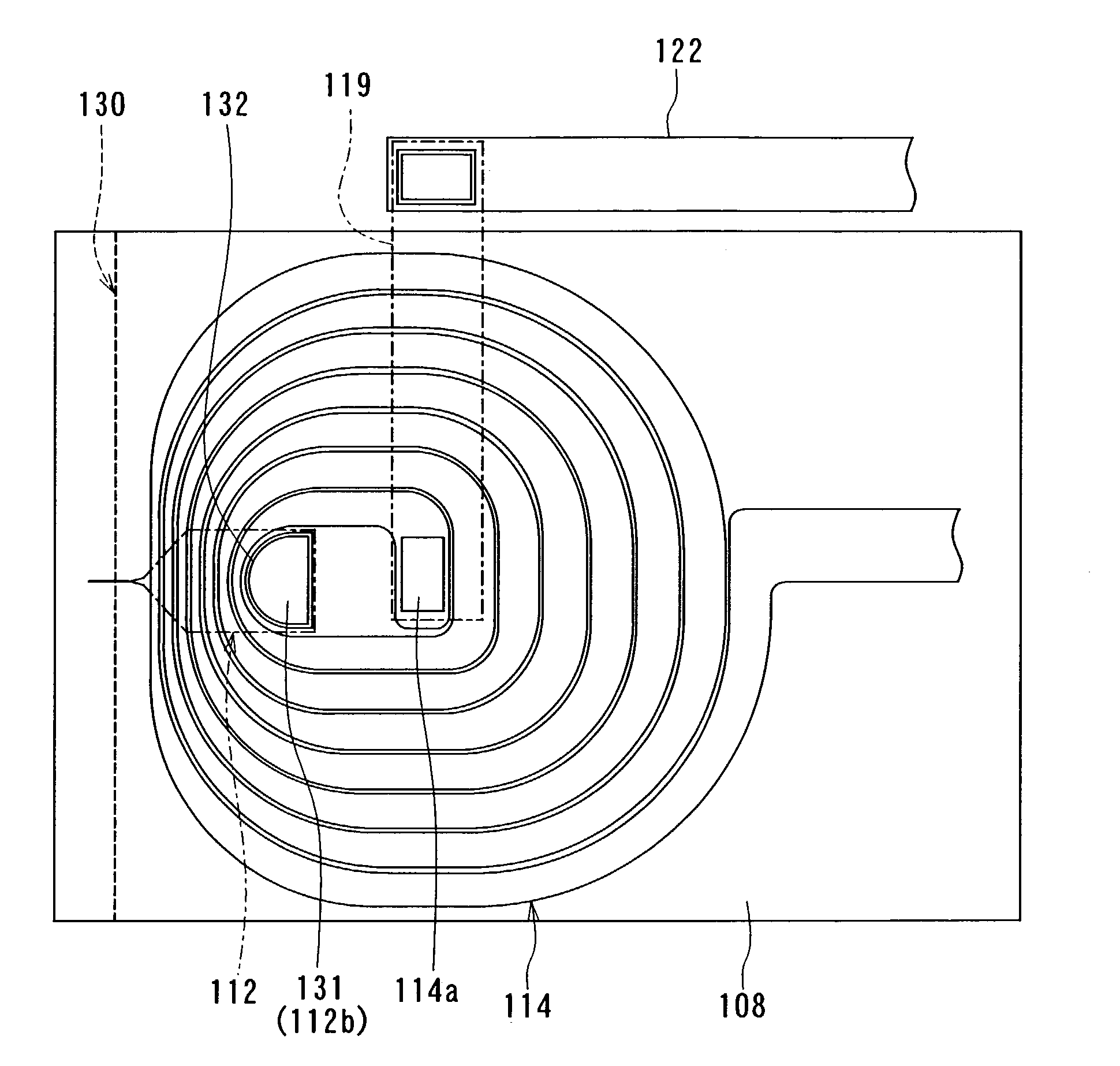
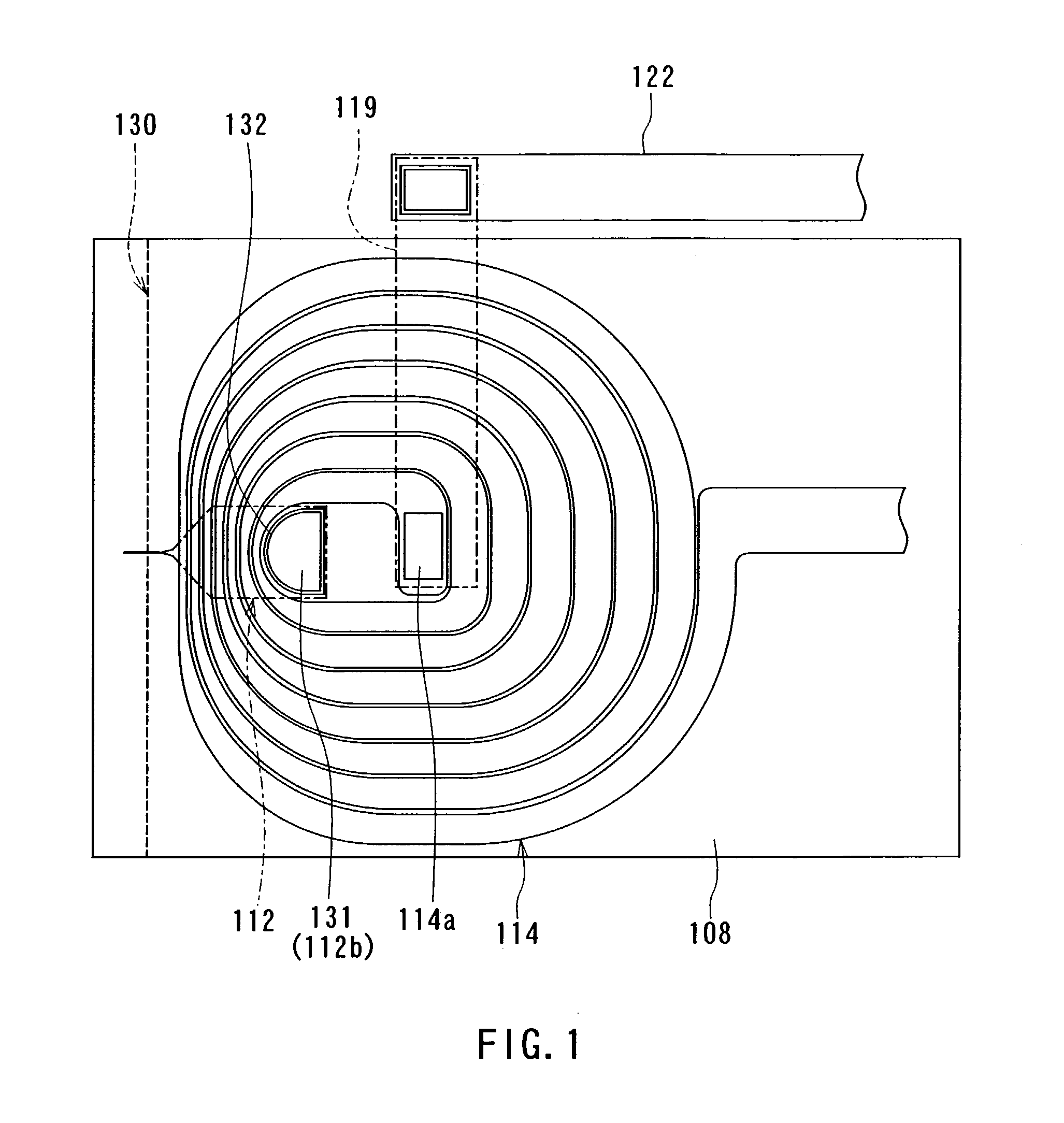
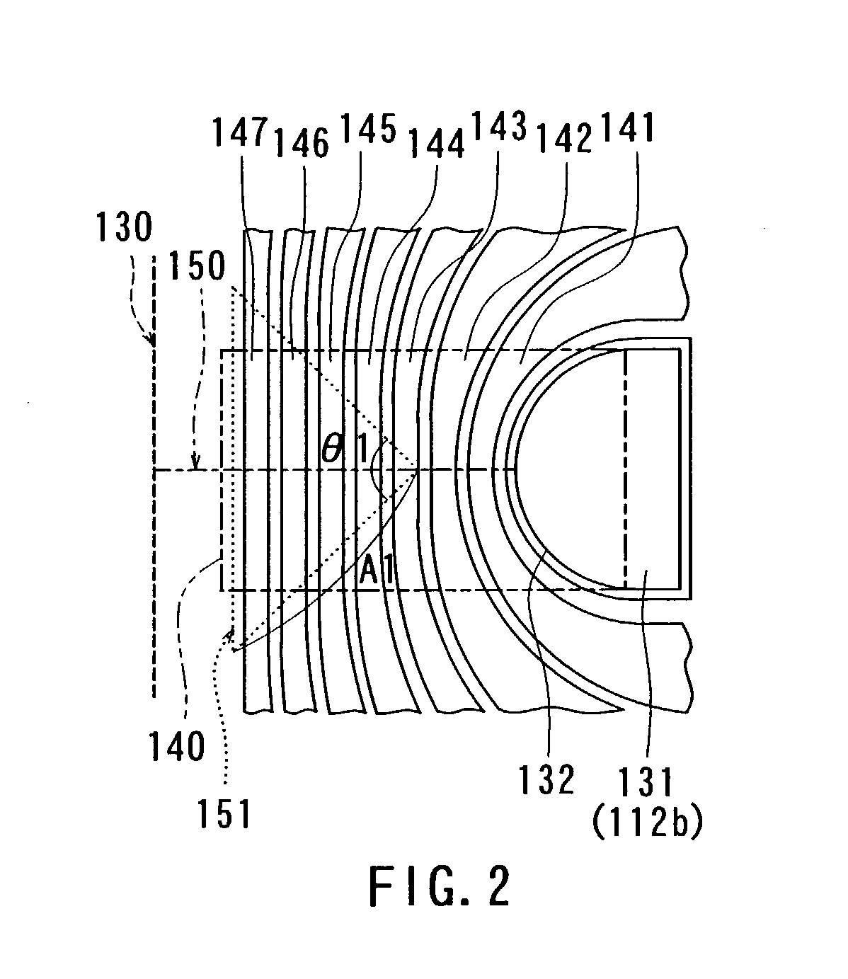
[0126] First, a method of manufacturing a thin-film magnetic head according to a first embodiment of the invention will now be described with reference to FIGS. 3A to 11A and FIGS. 3B to 11B. FIGS. 3A to 11A are cross sections each orthogonal to the air bearing surface and the top surface of the substrate. FIGS. 3B to 11B are cross sections of the magnetic pole portion each parallel to the air bearing surface.

[0127] In the method of manufacturing the thin-film magnetic head of the present embodiment, as shown in FIGS. 3A and 3B, an insulating layer 102 made of alumina (Al2O3), for example, is first deposited to a thickness of approximately 2 to 3 μm on a substrate 101 made of aluminum oxide and titanium carbide (Al2O3—TiC), for example. Next, a bottom shield layer 103 intended for a reproducing head, made of a magnetic material such as Permalloy, is formed to a thickness of approximately 2 to 3 μm on the insulating layer 102. The bottom shield layer 103 is ...

second embodiment

[0199] [Second Embodiment]

[0200] Now, a thin-film magnetic head and a method of manufacturing the same according to a second embodiment of the invention will be described with reference to FIG. 23, FIG. 24A to FIG. 38A, FIG. 24B to FIG. 38B, FIG. 39, and FIG. 40. FIG. 22 is a plan view showing the shape and arrangement of a coupling portion and a thin-film coil according to the present embodiment. Note that FIG. 23 shows the state before the air bearing surface is formed by lapping. FIG. 24A to FIG. 38A are cross sections each orthogonal to the air bearing surface and the top surface of the substrate. FIG. 24B to FIG. 38B are cross sections of the magnetic pole portions each parallel to the air bearing surface. FIGS. 39 and 40 are perspective views showing two examples of the configuration of the thin-film magnetic head according to the present embodiment excluding the overcoat layer.

[0201] In the method of manufacturing the thin-film magnetic head of the present embodiment, as sho...

third embodiment

[0260] [Third Embodiment]

[0261] Now, a thin-film magnetic head and a method of manufacturing the same according to a third embodiment of the invention will be described with reference to FIGS. 41A to 52A and FIGS. 41B to 52B. FIGS. 41A to 52A are cross sections each orthogonal to the air bearing surface and the top surface of the substrate. FIGS. 41B to 52B are cross sections of the magnetic pole portion each parallel to the air bearing surface.

[0262] The manufacturing method of the present embodiment is the same as that of the second embodiment up to the step of forming the intercoil insulating film 14.

[0263] Then, in the present embodiment, as shown in FIGS. 41A and 41B, a first conductive film made of Cu, for example, is formed to a thickness of, for example, 50 nm by sputtering, so as to cover the entire top surface of the laminate. On the first conductive film, a second conductive film made of Cu, for example, is formed by CVD to a thickness of 50 nm, for example. The second ...


PUM


Abstract

A thin-film magnetic head comprises a bottom pole layer, a top pole layer, a recording gap layer, and a thin-film coil. The thin-film magnetic head further comprises a coupling portion which is located away from an air bearing surface and establishes coupling between the bottom pole layer and the top pole layer. The coupling portion has an end face facing toward the air bearing surface. The end face includes a curved surface convex toward the medium facing surface. A part of the thin-film coil, which is disposed between the end face and the air bearing surface, has a minimum width of the thin-film coil in a position on a virtual line connecting the end face and the air bearing surface in the shortest distance, and increases in width with distance from the virtual line.

Description

BACKGROUND OF THE INVENTION [0001] 1. Field of the Invention [0002] The present invention relates to a thin-film magnetic head having at least an induction-type electromagnetic transducer, and a method of manufacturing same. [0003] 2. Description of the Related Art [0004] Recent years have seen significant improvements in the areal recording density of hard disk drives. In particular, areal recording densities of latest hard disk drives reach 80 to 100 GB / platter and are even on a pace to exceed that level. Thin-film magnetic heads are required of improved performance accordingly. [0005] Among the thin-film magnetic heads, widely used are composite thin-film magnetic heads made of a layered structure including a recording head having an induction-type electromagnetic transducer for writing and a reproducing head having a magnetoresistive element (that may be hereinafter called an MR element) for reading. [0006] In general, a recording head incorporates: a medium facing surface (air ...

Claims


Application Information

Patent Timeline
IPC IPC(8): G11B5/17G11B5/31
CPCG11B5/3116G11B5/17
Inventor SASAKI, YOSHITAKACRANDELL, DOUG
Owner HEADWAY TECH INC
Why Eureka
Try Eureka