
Battery Housing and Method of Manufacturing the Same

Inactive Publication Date: 2012-03-15
X CYTE
View PDF9 Cites 15 Cited by
  • Summary
  • Abstract
  • Description
  • Claims
  • Application Information

AI Technical Summary

Benefits of technology

[0030]A housing for a lithium based battery is described along with various methods for manufacturing the same. The battery housing is plated using DER as a substrate. The battery housing may meet the requirements for moisture and electrolyte barrier applications due to its excellent coverage characteristics. The plating process environment may not be aggressive, therefore it can be used to plate the exterior of batteries in a sequence of operations that may produce a seamless light weight package, maintaining the flexibility necessary to expand under extreme pressure, and thereby reducing the risk of explosion.

Problems solved by technology

Beginning in the early 1990's, however, the popularity of pick-up trucks and sports utility vehicles, which are not as fuel efficient as standard automobiles, has sparked new gasoline demand growth in the United States.
In transportation uses, there is little fuel substitution possible in the short term and only limited potential in the longer term, given current technology.
However, there are significant issues with these batteries that have made them commercially impracticable.
First, they have a low energy densitygasoline contains 100 times more energy per pound.
Second, they are bulky.
Third, they have a limited capacity.
Fourth, they are slow to charge.
Fifth, they have a short life.
Exasperating this problem, disposed batteries can be an environmental hazard if not properly recycled.
And sixth, they are expensive.
If external pressure is not exerted on these layers, the distance between the electrode surfaces becomes far from each other, failing to maintain the electric connection between the electrodes via the ion conducting layer, thereby deteriorating the battery properties.
The homogeneity of electrical resistance (and thereby current flow) across the surface of such an electrode is disturbed, leading to lithium plating, dendrite formation, and short-circuiting.
Lithium plating is dendritic and may cause the battery to short circuit.
), which may result in an explosion.
This variation in diameter of the jelly roll creates voids or lack of contact between the layers of the jelly roll (leading to the problems caused by inadequate stack pressure discussed above).
This process is well developed with good quality and output rates, but is expensive.
The process places limitations on how thin the metal housing can be, as the metal used must be sufficiently thick so as not to tear while it is being stretched.
The welding procedure used is highly complex, but well developed.
There is a high cost associated with both the welding equipment and the maintenance required.
This process also places a limitation on how thin the metal housing can be, since the metal must be sufficiently thick in order to bend.
As a consequence of these manufacturing limitations, the conventional metal housing comprises a large percentage of the volume and weight of a lithium-based battery, thus decreasing the energy density of the battery unit volume and unit weight.
This is an even more significant problem in the case of large format lithium batteries, where in order to draw a taller can the starting metal plate must be thicker and heavier.
Additionally, because of the fixed dimensions of the metal housing there is a large amount of void space in the container.
This void space implies lack of pressure on the laminated interface surfaces, and consequent underperformance and risk of explosion.
Another serious disadvantage of using a metal housing is a result of metal's burst pressure.
Because of lithium's higher capacity, there is a heightened danger of explosions associated with the use of a lithium battery.
When an excessive electrical or thermal load is applied, a short-circuit state occurs within the battery thus generating gas, and abnormally high internal pressure.
When the battery is overcharged, gas is generated within the battery due to decomposition of an electrolytic solution, and the internal pressure of the battery rises abnormally.
Due to the thickness of the metal can, pressure may accumulate until finally a catastrophic explosion results, wherein contents of the battery may be uncontrollably propelled.
However, the periodic and continuous release of gas pressure may, in some situations, permit electrolyte leakage containing salt and other particulate which may foul the resealable valve, and generally requires additional costly components.
There is usually some serious swelling of the cell before the seal breaks.
While these approaches for venting high pressure gas from the cell have resulted in the ability to vent excessive pressure, they have not optimized the volume consumed by the seal member, or lack an accurate rupture pressure mechanism.
Secondly, plastic can be easily formed into complex shapes for battery housings by extrusion, injection molding, thermoforming or other processes.
The migration of water vapor into a lithium battery and electrolyte solvent out of the battery will, generally, adversely affect a battery's electrical performance.
When the free acid component reacts with the lithium to form lithium fluoride (LiF) or the like and the lithium in the battery system is consumed, problems occur such that shelf stability or charge / discharge cycle characteristic deteriorates and a theoretical battery capacity cannot be obtained.
When the surface-treated moldings are bonded together with an epoxy or acrylic adhesive, the bonded portions may be affected and reduced in bonding strength by the electrolysis solution comprising organic solvents, in the case of lithium and other similar types of batteries.
Also, since those adhesives are hard, the bonded portions, when subject to an external force such as vibrations, may crack and leak the electrolytes.
Since lithium batteries must be strictly protected against moisture, degradation of the bonded portions has catastrophic consequences.
First, the blister package requires sealing a surface on all sides of the package. Since the performance of the battery depends much on the integrity of the seal, the sealing process is critical to the packaging operation.
Second, there are numerous variables associated with the sealing process that cannot be monitored in real time, making the process difficult at high speeds.
Third, folding and gluing of the sealing tabs is complex and can affect the electrode components and damage the seal.
Fourth, the package must be sealed under vacuum in an attempt to maintain constant pressure on the entire electrode interface area. Since the package has significant void area, the negative pressure inside the package will move some of the electrolyte solution to those void areas providing for discrete electrical paths affecting the performance of the cell. Because heat is applied to the package to seal it while applying the vacuum, there is a significant risk of displacement of electrolyte in the cell.
Fifth, the contact tabs must pass through the seal, creating a metal to plastic interface that is difficult to seal and monitor.
Sixth, the differential of pressure due to altitude influences the pressure exerted on the electrode interface area, and may affect the performance of the battery.

Method used


Image

  • Battery Housing and Method of Manufacturing the Same
  • Battery Housing and Method of Manufacturing the Same
  • Battery Housing and Method of Manufacturing the Same

Examples


Embodiment Construction

[0044]Those of ordinary skill in the art will realize that the following detailed description of the present invention is illustrative only and is not intended to be in any way limiting. Other embodiments of the present invention will readily suggest themselves to such skilled persons having the benefit of this disclosure.

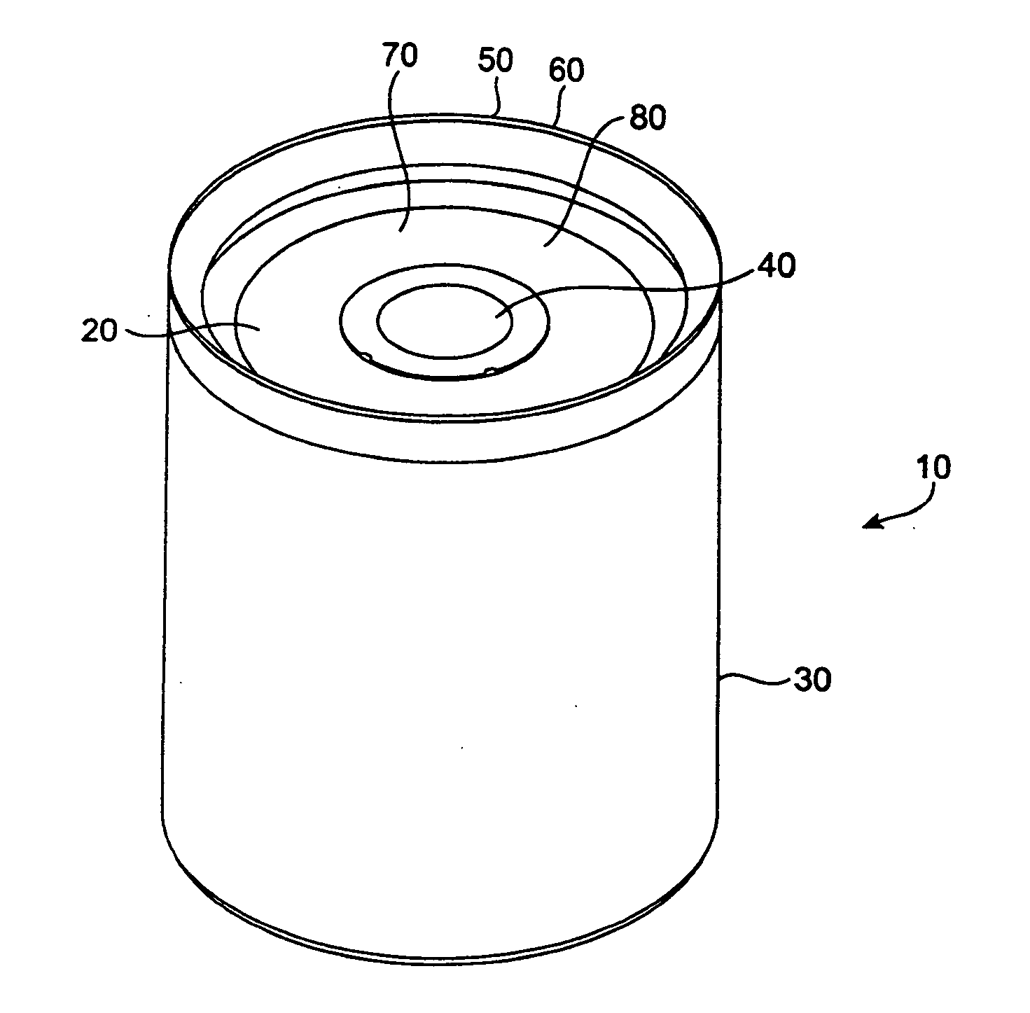
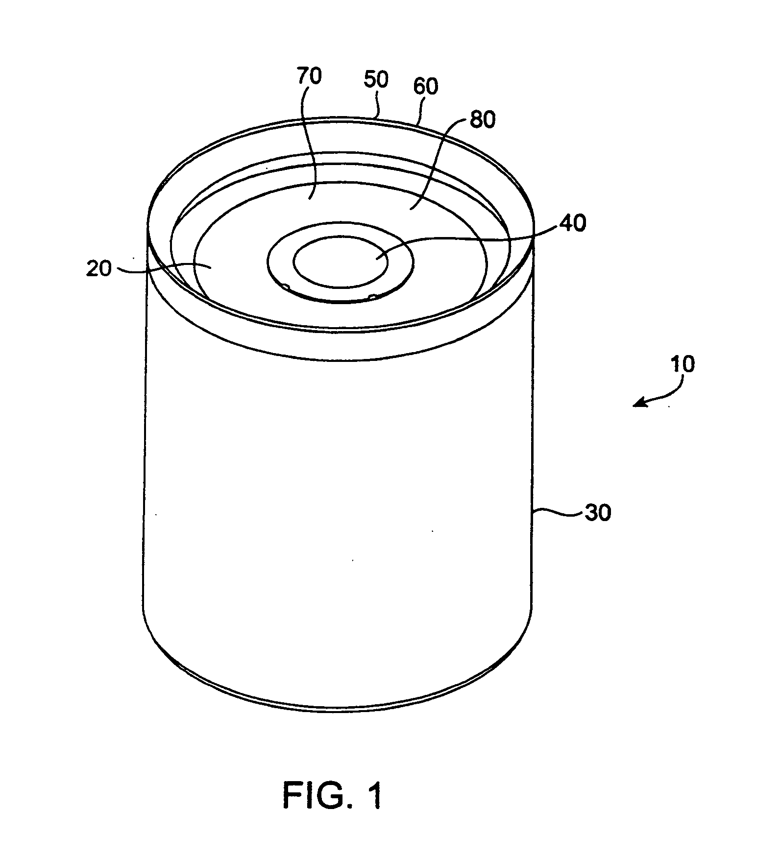
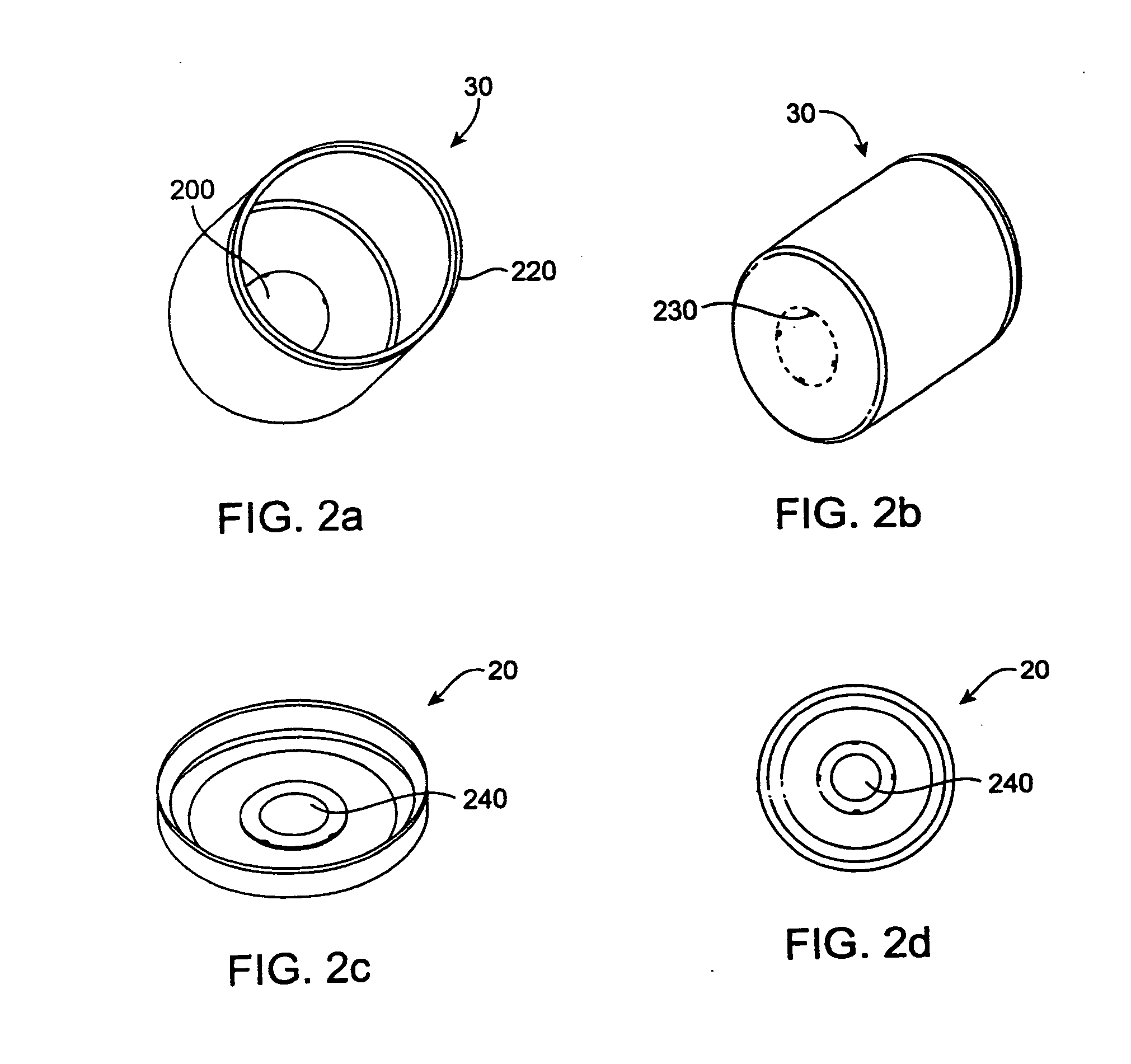
[0045]FIG. 1 is a perspective view of a plastic cylindrical housing 10 comprising a cap 20, a case 30, and a positive contact pad 40. In an embodiment, housing 10 may be manufactured using known molding techniques such as, e.g., injection molding, extrusion molding, blow molding, vacuum forming, and press molding. These methods may be inexpensive, have high productivity rates, and require low capital investment.

[0046]Housing 10 may comprise a thermoplastic that is chemically inert to most battery chemistries. In an embodiment, housing 10 comprises Polyvinylidine Difluoride, or PVDF. In an embodiment, housing 10 comprises polyethylene.

[0047]Housing 10 may be of any ...


PUM

PropertyMeasurementUnit
Thicknessaaaaaaaaaa
Thicknessaaaaaaaaaa
Pressureaaaaaaaaaa

Abstract

Disclosed is a housings for lithium based batteries, suitable for large format batteries, and a method of manufacturing such housings using direct electroplating resin technology. The housing, while maintaining stack pressure and acting as a moisture and electrolyte barrier, is lighter in weight, smaller in volume, and is safer than conventional metal housings. The manufacturing process is well suited for automation and is less expensive than current manufacturing processes.

Description

FIELD OF THE INVENTION[0001]The present invention relates generally to the field of batteries. More particularly, the present invention relates to the manufacture of housings for lithium based batteries, suitable for large format cylindrical and prismatic batteries, using direct electroplating resin technology.BACKGROUND OF THE INVENTION[0002]The United States' petroleum production peaked in 1970. Geologists have predicted that the peak of global oil production is imminent. While supply is diminishing, demand continues to increase. The industrialized countries are the largest consumers of oil but until 1998 had not been the most important growth markets for some years. The countries of the Organization for Economic Cooperation and Development (OECD), for instance, account for almost two-thirds of worldwide daily oil consumption. In contrast, however, oil demand in the OECD grew by some 11 percent over the 1991-97 period, while demand outside the OECD (excluding the Former Soviet Uni...

Claims


Application Information

Patent Timeline
IPC IPC(8): H01M10/04H01M10/052H01M10/058H01M10/36H01M50/119H01M50/121H01M50/124H01M50/129H01M50/133
CPCH01M2/0217Y10T29/49115H01M2/0262H01M2/0267H01M2/0275H01M2/0277H01M2/0287H01M2/0292H01M2/10H01M10/0413H01M10/052H01M10/058Y02E60/122Y02T10/7011H01M2/022Y02E60/10H01M50/107H01M50/103H01M50/124H01M50/1245Y02P70/50H01M50/133H01M50/121H01M50/129H01M50/119Y02T10/70
Inventor REIS, ANTONIO L.
Owner X CYTE
Learn More