Transverse flux switched reluctance motor and its control method

A switched reluctance motor and transverse flux technology, applied in the direction of AC motor control, control systems, electromechanical devices, etc., can solve the problems of excessive length of motor ends, noise and vibration, and large magnetic flux leakage, so as to improve efficiency and reduce Loss, the effect of increasing the power density

Active Publication Date: 2019-01-18
NANJING UNIV OF SCI & TECH
View PDF4 Cites 0 Cited by
  • Summary
  • Abstract
  • Description
  • Claims
  • Application Information

AI Technical Summary

Problems solved by technology

Based on the traditional transverse flux motor, Gu Chenglin proposed a transverse flux switched reluctance motor. The three-phase structure of the motor is three independent unit modules arranged along the axial direction, and the electrical angle difference between the modules is 120 degrees. However, the The motor has shortcomings such as too long end and large magnetic flux leakage
[0005] In short, the existing switched reluctance motors mainly have problems such as noise, vibration or large loss ([2] Song Shoujun, Ge Lefei, Liu Hucheng, etc. Multi-objective optimization method for the design of switched reluctance motors [J]. Journal of Electrotechnical Society, 2014, 29(5):197–204.), so there is still room for improvement in the accurate calculation of parameters such as motor structure and motor inductance

Method used


Image

  • Transverse flux switched reluctance motor and its control method
  • Transverse flux switched reluctance motor and its control method
  • Transverse flux switched reluctance motor and its control method

Examples


Embodiment 1

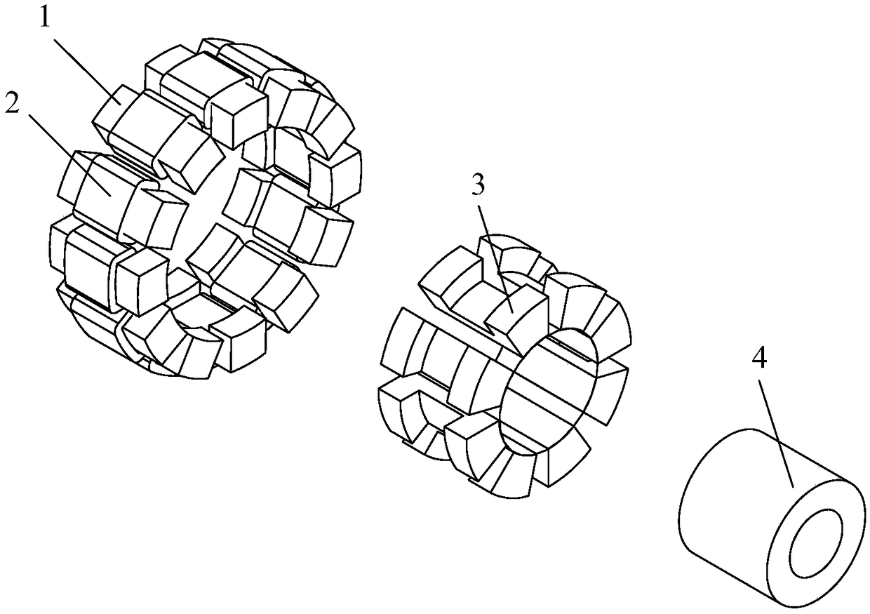
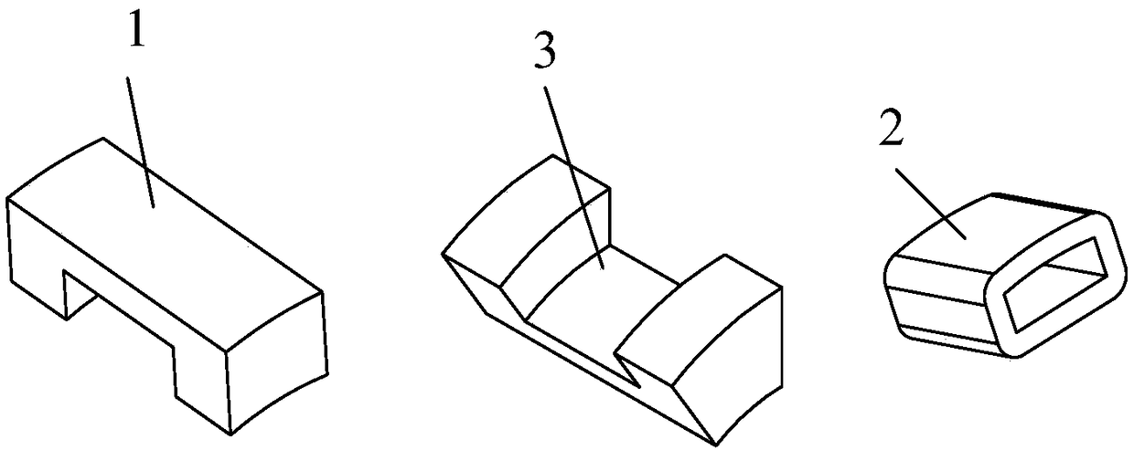
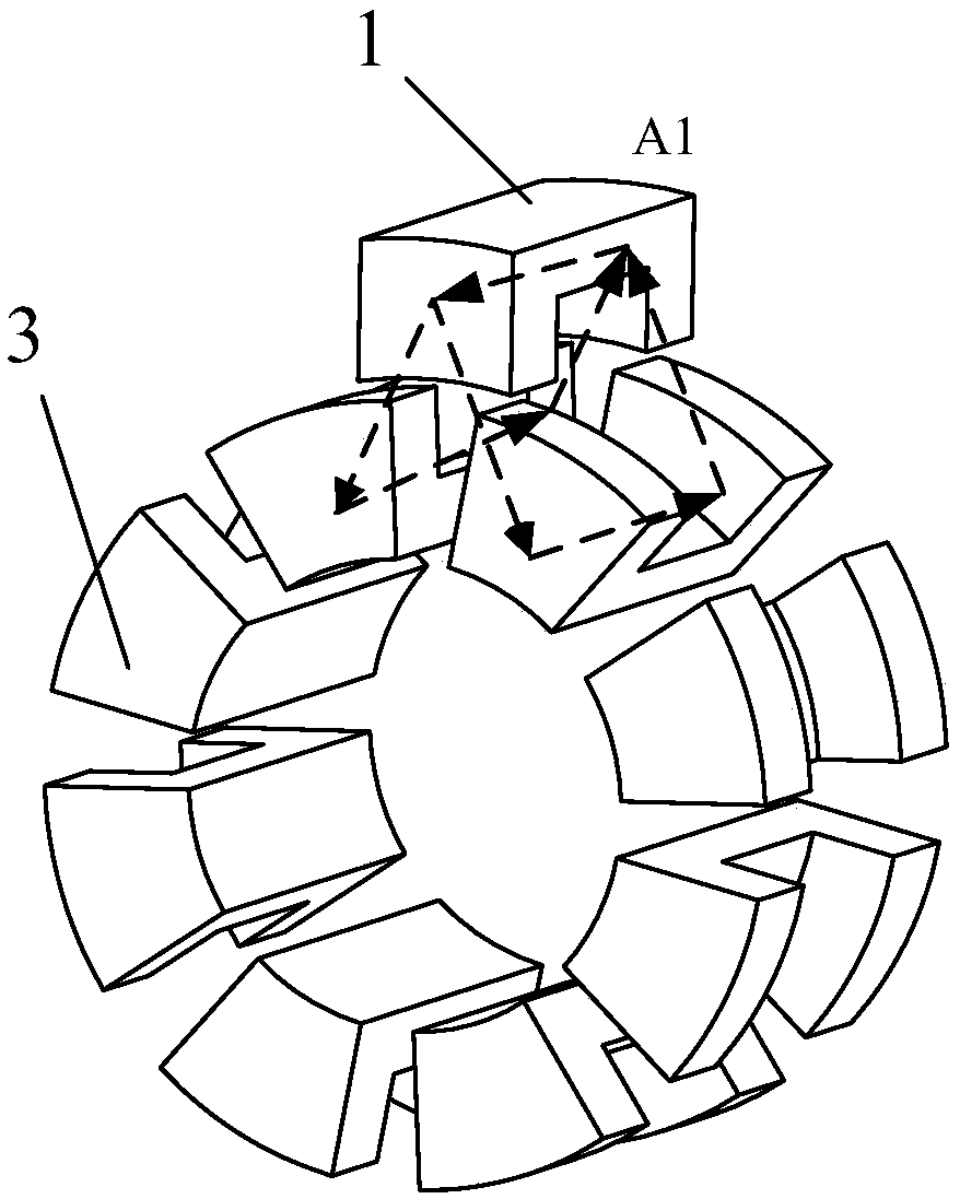
[0032] combine Figure 1-Figure 4 , for a 12 / 8 inner rotor three-phase transverse flux switched reluctance motor, the solid model of the motor is mainly composed of the following parts: stator core 1, stator armature winding 2, rotor core 3 and magnetic material rotor The sleeve consists of 4. Each stator is composed of stator core 1 and stator armature winding 2, and is evenly arranged along the circumferential direction. Each stator core 1 has the same size, and is made of silicon steel sheets, and is pasted and installed in a non-magnetic material sleeve with glue to form a The stator as a whole; the stator armature winding 2 adopts a centralized annular armature winding, and is wound in the U-shaped slot of the stator core 1, and is separated by three armature windings to form a phase; the rotor part includes rotor cores uniformly arranged along the circumferential direction 3 and non-magnetically conductive rotor cylinder 4, each rotor core 4 has the same size, and is ma...

Embodiment 2

[0034] combine Figure 1-Figure 4 , for the 12 / 8 inner rotor six-phase transverse flux switched reluctance motor, the solid model of the motor is mainly composed of the following parts: stator core 1, stator armature winding 2, rotor core 3 and magnetic material rotor The sleeve consists of 4. Each stator is composed of stator core 1 and stator armature winding 2, and is evenly arranged along the circumferential direction. Each stator core 1 has the same size, and is made of silicon steel sheets, and is pasted and installed in a non-magnetic material sleeve with glue to form a The stator as a whole; the stator armature winding 2 adopts a centralized annular armature winding, and is wound in the U-shaped slot of the stator core 1, and is separated by 6 armature windings to form a phase; the rotor part includes rotor cores uniformly arranged along the circumferential direction 3 and non-magnetically conductive rotor cylinder 4, each rotor core 4 has the same size, and is made o...


PUM


Abstract

The invention discloses a transverse flux switching reluctance motor and a control method thereof. The motor section comprises stator cores, rotor cores, stator windings, non-magnetic rotor sleeves and bearings. A stator comprises Ns stator cores and Ns circular armature windings embedded in the stator core structures, Ns stator windings can be in symmetrically grouping at the circumference, composing an m-phase winding, wherein Ns=2mk, k is an arbitrary integer greater than 1. A rotor comprises Nr rotor cores, and each rotor core is uniformly disposed on the non-magnetic rotor sleeve at the circumference, wherein Nr=Ns+ / -2k. Each phase of winding is independently energized with direct current in sequence according to the calculated conduction and the extinction angle, forming a reluctance torque of the motor to drive the rotation of the motor. The transverse flux motor is composed of the arrangement of the stator and the rotor and the main flux path, making the inexistence of mutual inductance in the motor. Furthermore, combined with electrification sequence and method of each phase of the winding of the motor, the change of the reluctance of motor for driving of the rotation of motor is achieved, and the power density of motor is raised.

Description

technical field [0001] The invention belongs to the field of motors, and in particular relates to a transverse flux switched reluctance motor and a control method thereof. Background technique [0002] Due to its simple structure, reliable operation, high efficiency, low cost and other advantages, switched reluctance motor has become the main research focus at home and abroad. In recent years, many scholars at home and abroad have made remarkable achievements in the structure and control of switched reluctance motors, and have successfully applied switched reluctance motors to many fields such as electric vehicles, industrial and mining machinery, and textile machinery. Since there is no permanent magnet or winding on the motor rotor, it has high reliability and is suitable for harsh environments or occasions. In terms of performance, switched reluctance motors have the advantages of frequent forward and reverse rotation, good speed regulation performance, strong overload c...

Claims


Application Information

Patent Timeline
Patent Type & Authority Patents(China)
IPC IPC(8): H02K29/03H02P25/08
CPCH02K29/03H02K2213/03
Inventor 颜建虎汪盼费晨言钊张尚坤杨凯
Owner NANJING UNIV OF SCI & TECH
Why Eureka
Try Eureka